Mode
l 5315A/ B
Service
~8
1.
Test
Pr
ocedu
re 4 Mk rocompute
r,
Ois
pl
..
y,
.. nd 0 ..... Bus
6-82.
To
verify
the
proper
operatio
n of A1Ul
Microcomputer,
A2
Display assembly
and
the
interconnecting data bus,
perform
the
following
procedures:
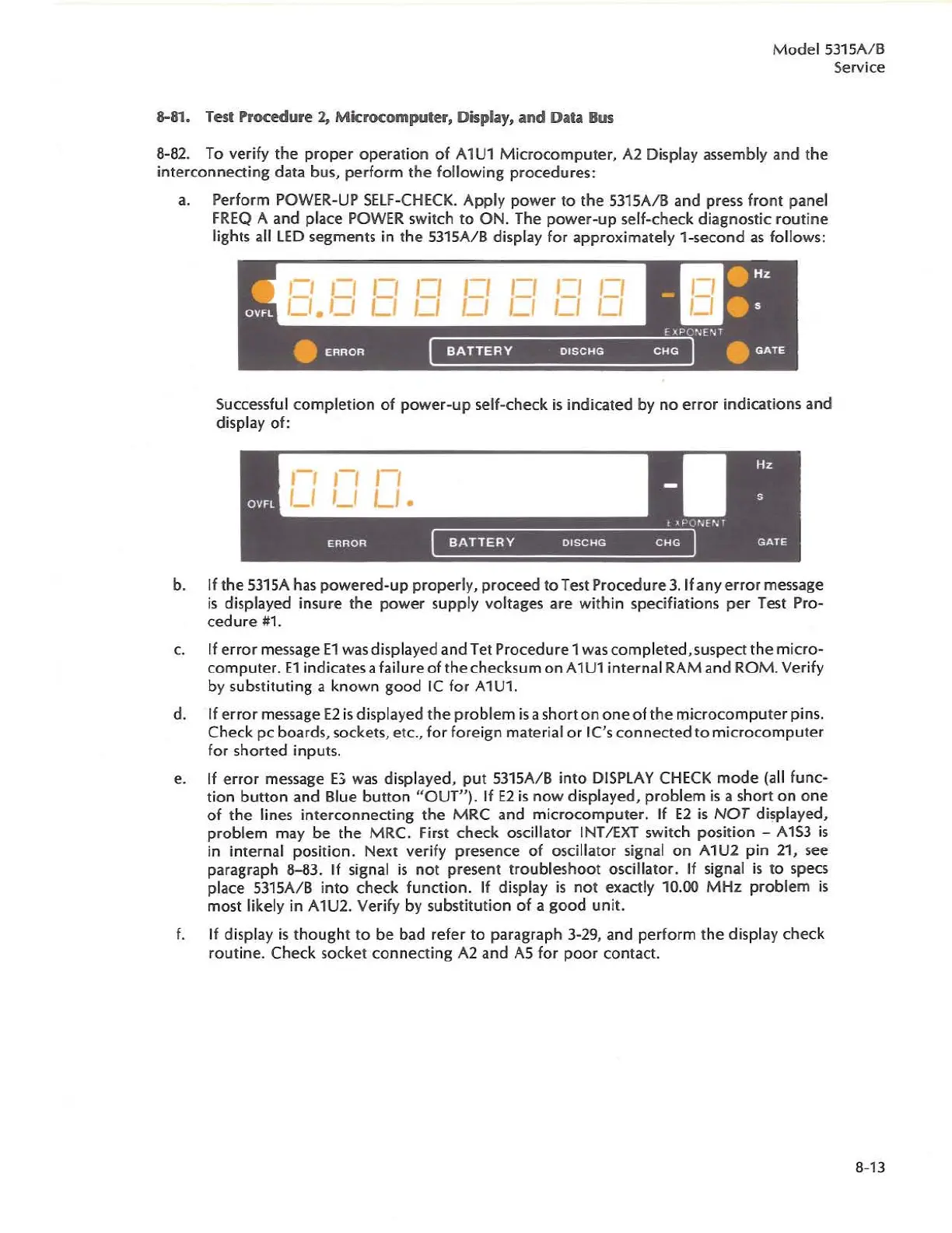
a.
Perform POWER-UP SElf-CHECK. Apply
power
to
the
53
1
5A/B
and
press front panel
fREQ A
and
place POWER switch
to
ON.
The
power-up
self-check diagnostic
routine
lights all
LED
segments in
the
5315A/B display for approximately 1
-second
as follows:
,-,
,-,
,-,
,-,
,-,
LI
I ,
,-,
BATTERY
DISCHG
CHG
Successful
completion
of
power-up
self-check
is
indicated by
no
error
ind
ications
and
display of:
BATTERY
DISCHG
CHG
b.
If
the
5315A
has
powered-up
properly,
proceed
to
Test
Procedure
3.
If
any
error
message
is
displayed insure
the
power
supply voltages
are
within specifiations
per
Test Pro-
cedure
#
1.
c. If
error
message
E1
was displayed
and
Tet
Procedure
1 was
completed
, suspect
the
micro-
computer.
E1
indicates a failure of
the
checksum
on
A1U1
internal
RAM
and
ROM. Veri
fy
by substituting a known
good
IC
for A1U1.
d.
If
error
message
E2
is
display
ed
the
problem
is
a short on
one
of
the
microcomputer
pins.
Check
pc boards, sockets, etc., for foreign material
or
Ie's
connected
to
mi
c
rocomputer
for
shorted
inputs.
e.
If
error
message
E3
was displayed,
put
5315A/ 8 into
DISPLAY
CHECK
mode
(a
ll
func-
tion
button
and Blue
button
"OUT").
If
E2
is
now displayed,
problem
is
a
short
on
one
of
the
lines
interconnecting
the
MRC
and
microcomputer.
If
E2
is
NOT
di~played,
problem
may
be
the
MRC. first
check
oscillator
INT/EXT
switch position -
A1S3
is
in internal position. Next verify
presence
of
oscillator signal
on
A1U2 pin 21,
see
paragraph 8-83.
If
signal
is
not
present
troubleshoot
oscillator.
If
signal
is
to
specs
pl
ace
5315A/8 into
check
function. If display
is
not
exactly 10.00 MHz
problem
is
most likely in A1U2. Verify by substitution
of
a
good
unit.
f.
If
display
is
thought
to
be
bad refer to paragraph 3-29,
and
perform
the
display
check
rout
i
ne
.
Check
socket
connecting
A2
and
A5
for
poor
contact.
8-13