Model
5315A/ B
Servi
ce
8-'4
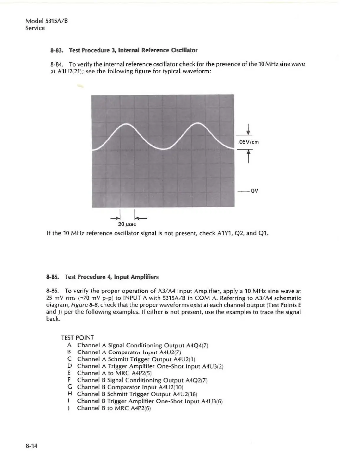
8-83. Test Procedure
3,
Internal Reference Oscillator
6·84. To ve
rif
y
the
internal reference oscill
ator
chec
k
for
the presence
of
the
10
MHz
sin
ewave
at A1U2(
21
);
see
the foll
owing
fig
ur
e
for
typi
ca
l wavefor
m:
20
J,l.sec
If
the 10
MHz
referen
ce
oscillator signal
is
not
present, check A1Y1, Q2, and Q1 .
8-85. Test Procedure
4,
Input Amplifiers
8·86. To ve
rif
y the
pr
oper
operation
of
A3/A4
Input
Amp
lifier,
app
ly a 10 M Hz sine wave
at
25
mV
rms
("
70
mV
pop
)
to
INPUT A wi
th
53
1
5A
/ B
in
COM
A. Refe
rring
to A3/ A4 schematic
diagram,
Figure 8-8, check that
th
e
proper
waveforms exi
st
at each channel
output
(Test Points E
and
J)
per
the
following
exampl
es.
If
eit
h
er
is
n
ot
present, use
the
exampl
es
to
trace
the
signal
back.
TE
ST
POINT
A Channel A Sign
al
Conditio
n
ing
Output
A4Q4(7)
B Channel A ComparalOr I
nput
A4U2{7)
C
Channel A Schmit! Trigger
Output
A4U2(1 )
D Channel A Trigger
Am
plifier
One-Shot
Inp
ut
A4U3(2)
E Channel A
to
MRC
A4
P2
(S)
F Channel 8 Signal
Conditioning
Ou
tput
A4Q2(7)
G Channel B
Comparator
Input
A4U2(10)
H Channel 8 Schmitt Trigger
Output
A4U2
(16)
I Channel 8 Trigger
Amplifier
One-Shot
Input
A4U3(6)
J Channel 8
to
MRC
A4P2(6)