53
Label: NULL RealNextHop: 192.168.3.2
BkLabel: NULL BkNextHop: N/A
Tunnel ID: Invalid Interface: vlan-interface 200
BkTunnel ID: Invalid BkInterface: N/A
Configuring BFD for RIP (bidirectional detection in BFD control
packet mode)
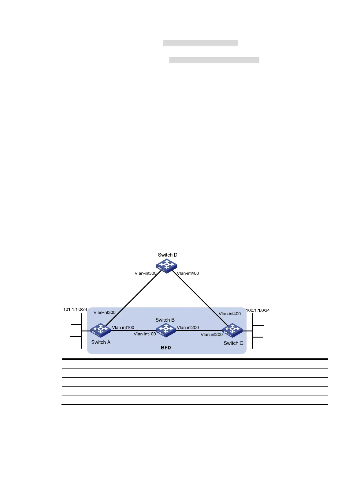
Network requirements
As shown in Figure 13, VLAN-interface 100 of Switch A and VLAN-interface 200 of Switch C run RIP
process 1.
VLAN-interface 300 of Switch A runs RIP process 2. VLAN-interface 400 of Switch C, and
VLAN-interface 300 and VLAN-interface 400 of Switch D run RIP process 1.
Configure a static route destined for 100.1.1.0/24 on Switch A, configure a static route destined for
101.1.1.0 / 24 o n S wi t ch C , a n d e n a b l e s t a t i c ro u t e re distribution into RIP on Switch A and Switch C so
Switch A can learn two routes destined for 100.1.1.0/24 through VLAN-interface 100 and
VLAN-interface 300, and uses the one through VLAN-interface 100.
Enable BFD on VLAN-interface 100 of Switch A and VLAN-interface 200 of Switch C. When the link over
VLAN-interface 100 fails, BFD can quickly detect the link failure and notify RIP so RIP deletes the
neighbor relationship and the route information received learned on VLAN-interface 100, and uses the
route destined for 100.1.1.0/24 through VLAN-interface 300.
Figure 13 Network diagram
Device Interface IP address
Device
Interface
IP address
Switch A Vlan-int300 192.168.3.1/24 Switch B Vlan-int100 192.168.1.2/24
Vlan-int100 192.168.1.1/24
Vlan-int200 192.168.2.1/24
Switch C Vlan-int200 192.168.2.2/24
Switch D
Vlan-int300 192.168.3.2/24
Vlan-int400 192.168.4.2/24 Vlan-int400 192.168.4.1/24
Configuration procedure
1. Configure IP addresses for interfaces. (Details not shown.)
2. Configure basic RIP and enable static route redistribution into RIP so Switch A and Switch C have
routes to send to each other:
 Loading...


