EasyManuals Logo

HP Apollo a6000 Chassis User Manual

HP Apollo a6000 Chassis
62 pages
To Next Page IconTo Next Page
To Previous Page IconTo Previous Page
Page #28 background imageLoading...
Page #28 background image
Removal and replacement procedures 28
4.
Install the power supplies into the power shelf, if needed.
NOTE: If additional clearance is required to install power cables, loosen the thumb screw on
either side of the shelf and slide the shelf out while installing the cables. Use caution to avoid
bending the shelf.
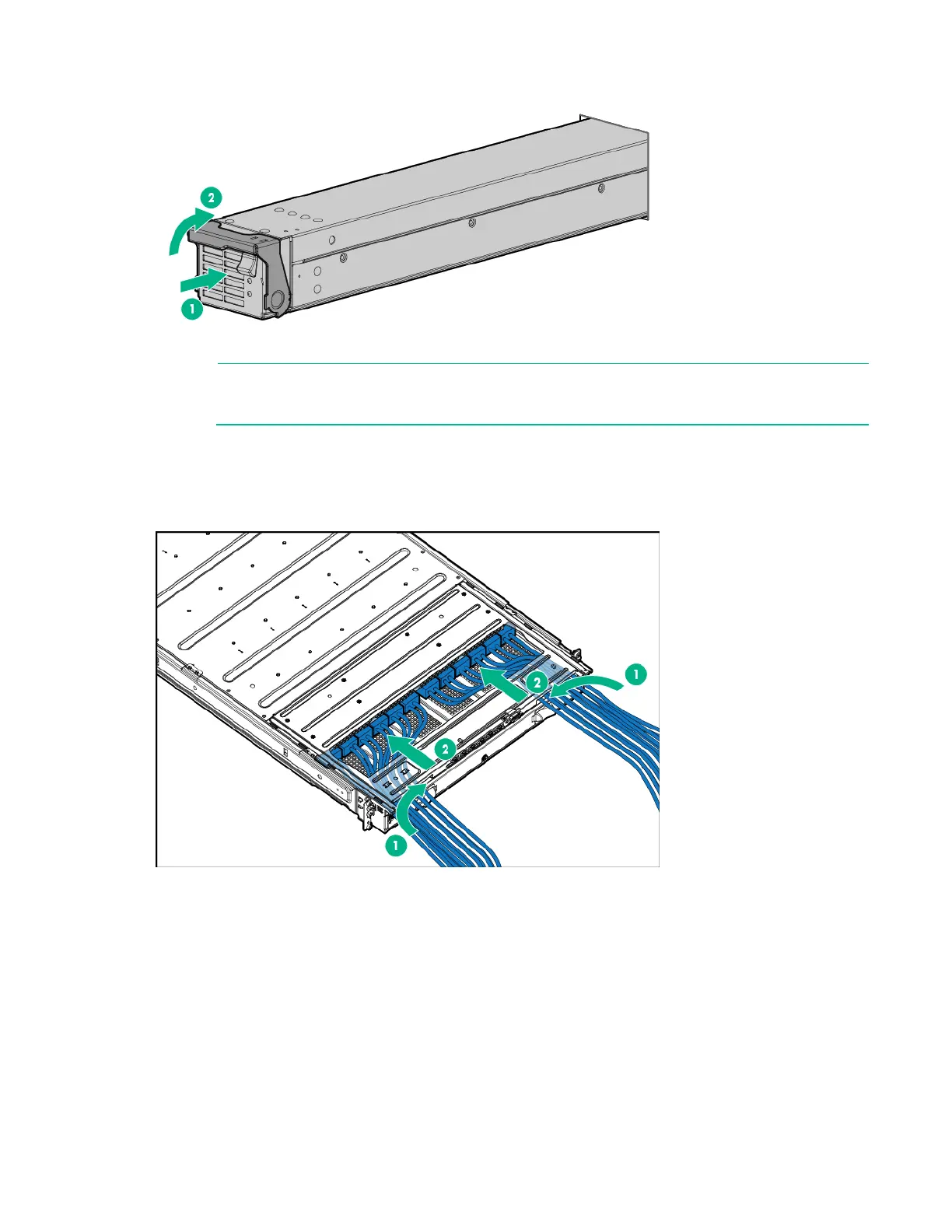
5. Remove the power supply vent cover.
6. Install the 12V DC power cables.
a. Insert the cable through the wide opening on either end of the power shelf, and then connect it to
the appropriate connector.

Table of Contents

Questions and Answers:

Question and Answer IconNeed help?

Do you have a question about the HP Apollo a6000 Chassis and is the answer not in the manual?

HP Apollo a6000 Chassis Specifications

General IconGeneral
Form FactorRack
Number of Nodes Supported4
Processor SupportIntel Xeon Scalable processors
ManagementIntegrated Lights-Out (iLO)
Memory SupportVaries by node. Supports DDR4 memory.
Drive BaysVaries by node. Supports SAS/SATA/SSD drives.
Expansion SlotsVaries by node. Supports PCIe slots.
NetworkingVaries by node. Supports Ethernet and InfiniBand.

Related product manuals