Removal and replacement procedures 34
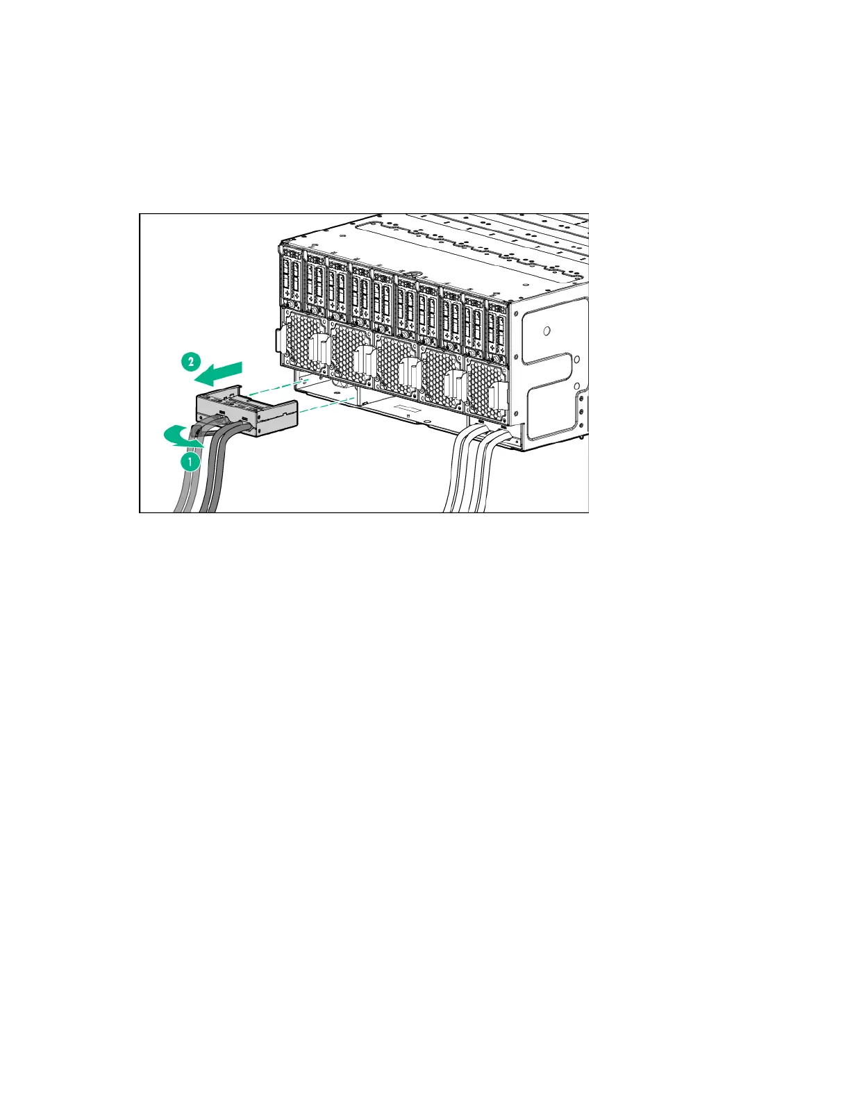
Power cage
To remove the component:
1. Power down all servers ("Power down the server" on page 20).
2. Remove the management module ("Management module LEDs and buttons" on page 45,
"Management module" on page 33).
3. Remove the power cage.
To replace the component, reverse the removal procedure.
Power backplane
To remove the component:
1. Power down all servers ("Power down the server" on page 20).
2. Disconnect all cables from the chassis.
3. Remove all servers ("Remove the server" on page 20).
4. Remove the management module ("Management module LEDs and buttons" on page 45,
"Management module" on page 33).
5. Remove both power cages ("Power cage" on page 34).
6. Remove all fan modules ("System fans" on page 31).
7. Remove the chassis from the rack (on page 22).
8. Remove the I/O modules ("I/O module" on page 32).
9. Place the chassis on a flat, sturdy surface to support the chassis.