EasyManuals Logo

HP Apollo a6000 Chassis User Manual

HP Apollo a6000 Chassis
62 pages
To Next Page IconTo Next Page
To Previous Page IconTo Previous Page
Page #36 background imageLoading...
Page #36 background image
Removal and replacement procedures 36
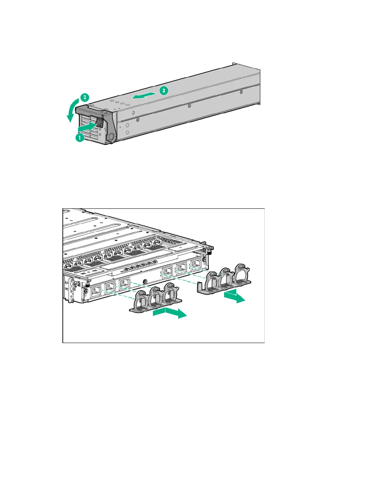
Power supplies
Remove the component as indicated.
To replace the component, reverse the removal procedure.
Power cable retention brackets (left and right)
Remove the component as indicated.
To replace the component, reverse the removal procedure.
Power management module
To remove the component:
1. Power down servers installed in the chassis connected to the power shelf ("Power down the server"
on page 20).
2. Remove the safety guard.
3. Remove the DC power cables.

Table of Contents

Questions and Answers:

Question and Answer IconNeed help?

Do you have a question about the HP Apollo a6000 Chassis and is the answer not in the manual?

HP Apollo a6000 Chassis Specifications

General IconGeneral
Form FactorRack
Number of Nodes Supported4
Processor SupportIntel Xeon Scalable processors
ManagementIntegrated Lights-Out (iLO)
Memory SupportVaries by node. Supports DDR4 memory.
Drive BaysVaries by node. Supports SAS/SATA/SSD drives.
Expansion SlotsVaries by node. Supports PCIe slots.
NetworkingVaries by node. Supports Ethernet and InfiniBand.

Related product manuals