EasyManuals Logo

HP Apollo a6000 Chassis User Manual

HP Apollo a6000 Chassis
62 pages
To Next Page IconTo Next Page
To Previous Page IconTo Previous Page
Page #45 background imageLoading...
Page #45 background image
Component identification 45
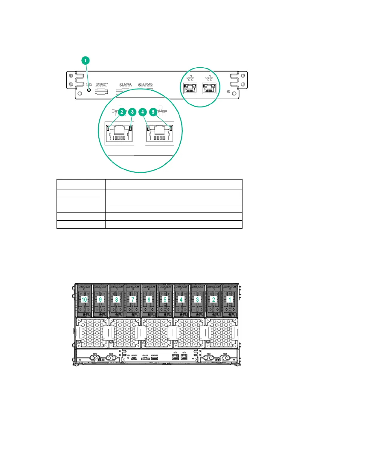
Management module LEDs and buttons
Item
Description
1
UID LED
2
iLO network 1 link LED
3
iLO network 1 activity LED
4
iLO network 2 link LED
5
iLO network 2 activity LED
I/O module bay numbering
I/O modules are specific to each server and are installed in the rear of the chassis.
The chassis has ten I/O module bays located in the rear of the chassis.
For more information about product features, specifications, options, configurations, and compatibility,
see the product QuickSpecs on the Hewlett Packard Enterprise website (http://www.hpe.com/info/qs).
Power shelf rear panel components

Table of Contents

Questions and Answers:

Question and Answer IconNeed help?

Do you have a question about the HP Apollo a6000 Chassis and is the answer not in the manual?

HP Apollo a6000 Chassis Specifications

General IconGeneral
Form FactorRack
Number of Nodes Supported4
Processor SupportIntel Xeon Scalable processors
ManagementIntegrated Lights-Out (iLO)
Memory SupportVaries by node. Supports DDR4 memory.
Drive BaysVaries by node. Supports SAS/SATA/SSD drives.
Expansion SlotsVaries by node. Supports PCIe slots.
NetworkingVaries by node. Supports Ethernet and InfiniBand.

Related product manuals