Chapter 3 Installing the switch 35
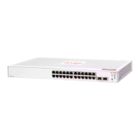
Figure 16: Connecting DC power to the switch
4. Replace the transparent protective cover on the DC connector terminals.
5. Turn on the DC power source lines or reconnect them to the DC circuit.
Check LEDs for proper switch operation
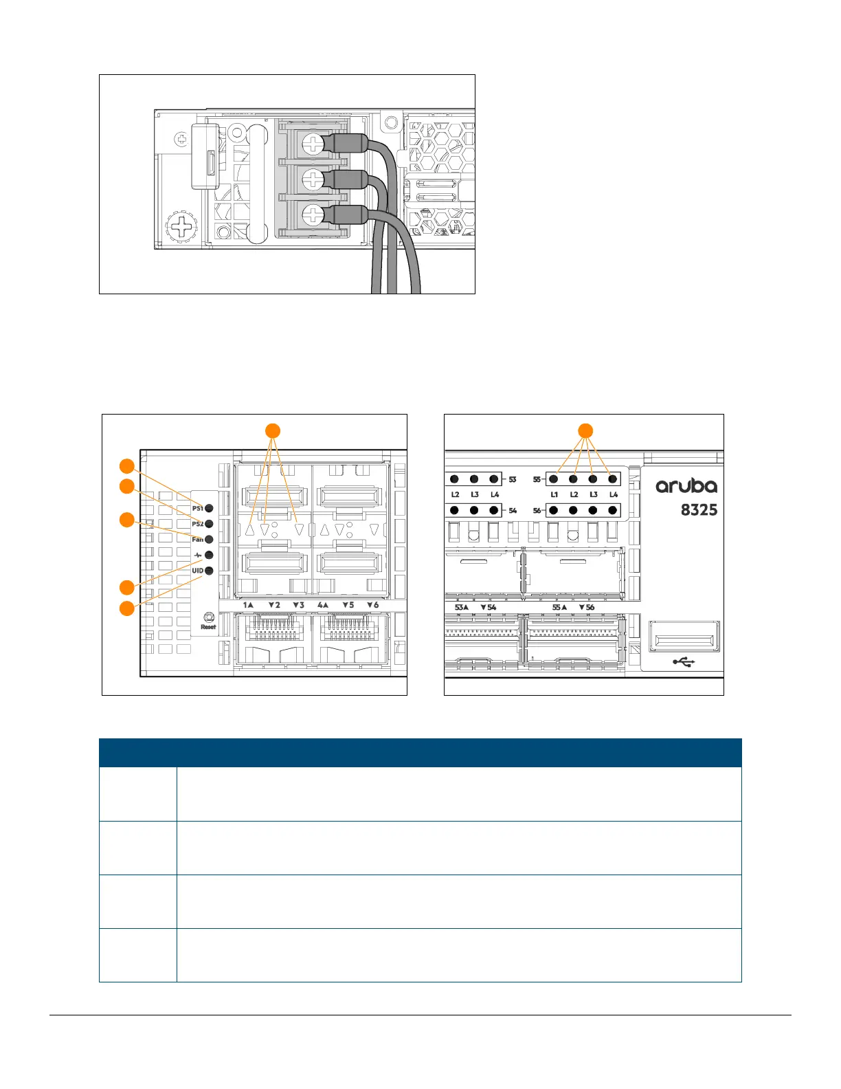
Figure 17: Chassis LEDs for the Aruba 8325-48Y8C (JL624A, JL625A, JL857A, and JL858A)
Table 23: Chassis LED labels for the Aruba 8325-48Y8C (JL624A, JL625A, JL857A, and JL858A)
Label Description
1 SFP28 Port LEDs:
Off, unless a network cable is connected and the port is receiving link beat.
2 PS1 LED:
Green after power on, unless the power supply is in a fault state, or not receiving power.
3 PS2 LED:
Green after power on, unless the power supply is in a fault state, or not receiving power.
4Fan LED:
Green after power on, unless a fan on the back of the unit is in a fault state.

 Loading...