Chapter 5 Replacing components 51
2. Remove the new fan assembly from its packaging, being careful to not touch any of the circuitry on the board.
3. Loosen the retaining screw on the fan assembly in the 8325-32C. For a fan assembly in the 8325-48Y8C, pull
the release latch on the inside of the fan assembly handle.
4. Grasping the handle of the failed fan assembly, pull it straight out to remove it from its slot.
5. Insert the new fan assembly fully into the slot so that its face plate is flush with the back face of the switch. If
the switch is connected to an AC power source, the fan assembly should immediately start running.
6. For the 8325-32C fan assembly, engage the retaining screw and tighten it. Be sure to not over-tighten the
screw.
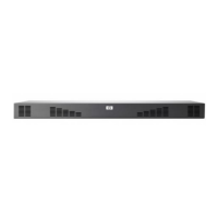
Figure 33: Replacing a failed fan assembly
Table 30: Replacing a failed fan assembly labels and descriptions
Label Description
1 Fan assembly release latch
2 Fan assembly handle
3 Fan assembly retaining screw

 Loading...