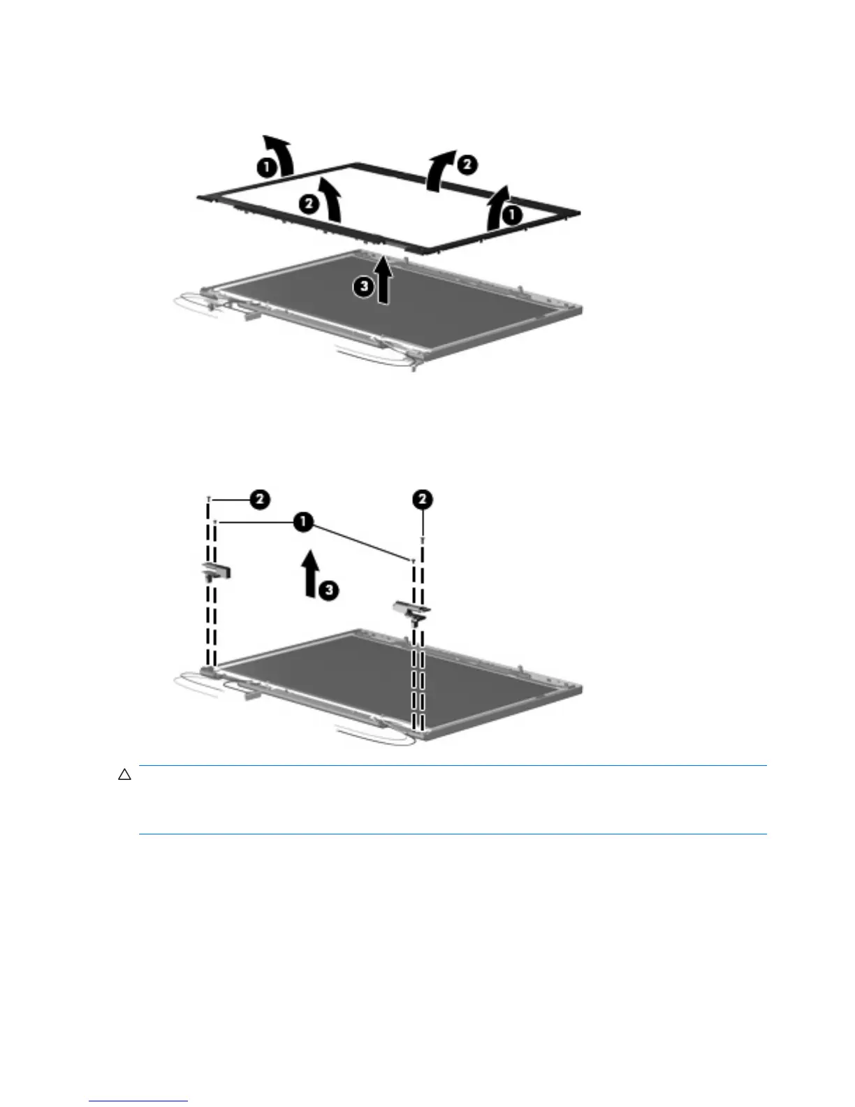
11. Remove the display bezel (3). The display bezel is available using spare part number
446420-001.
12. Remove the two Phillips PM2.5×4.0 screws (1) and the two Phillips PM2.5×6.0 screws (2) that
secure the display hinge to the display panel.
13. Remove the display hinges (3). The left and right display hinges are available using spare part
number 446417-001.
CAUTION: When installing the display assembly, be sure that the wireless antenna cable routed out
of the display left hinge is routed and arranged properly. This antenna cable has a grounding sleeve
(1) and an exposed section of cable (2). The grounding sleeve must completely cover the exposed section
of cable, and must be in contact with the grounding clip (3) on the left display hinge.
Failure to follow these routing instructions can result in degradation of the computer's WLAN and WWAN
performance.
74 Chapter 4 Removal and replacement procedures
 Loading...