7-12 www.hp.com Technical Reference Guide
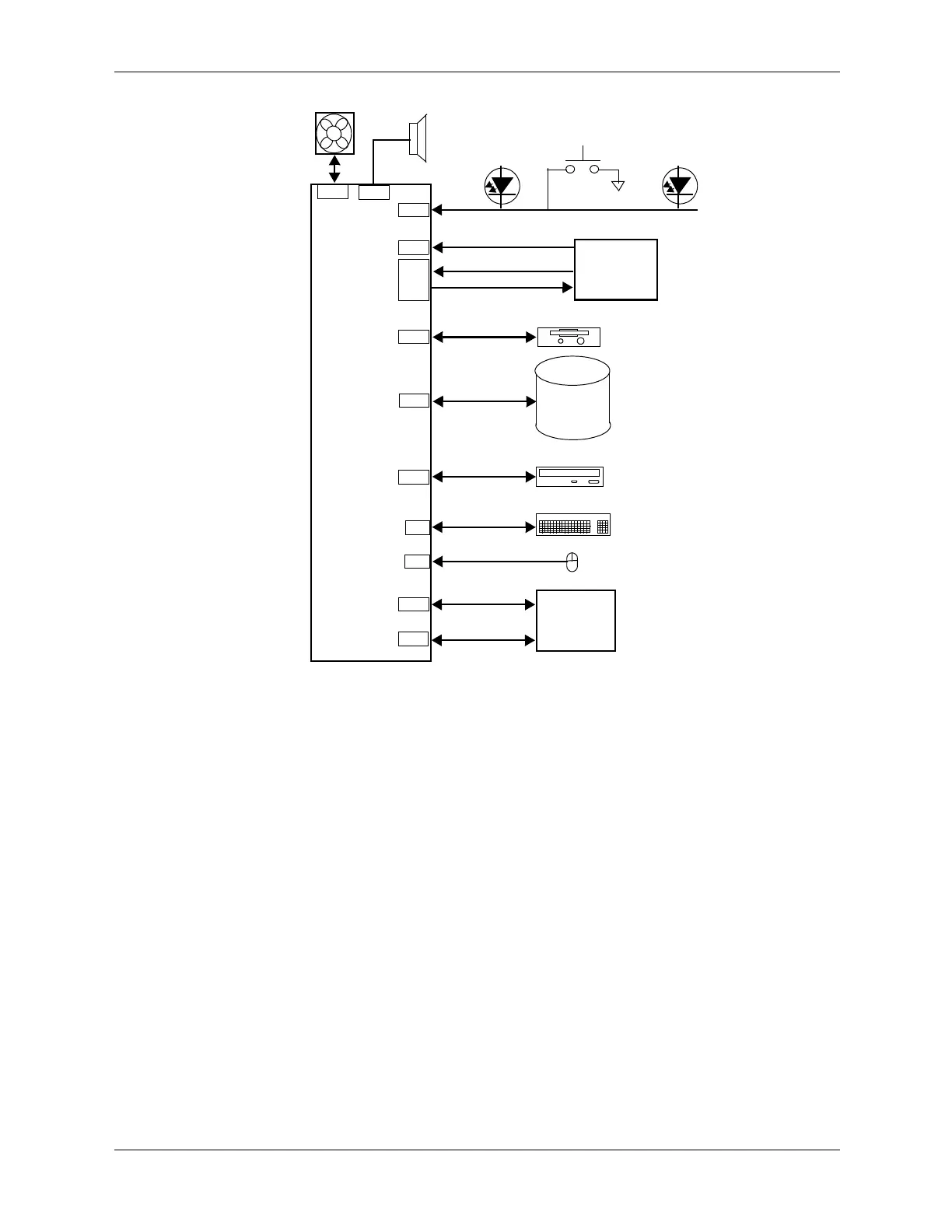
Power and Signal Distribution
NOTES:
See Figure 7-8 for header pinout.
Figure 7-6. SFF / ST Form Factor Signal Distribution Diagram
P8
+12 VccP
Power LED
P1
Power
P6
P5
P3
Supply
Assembly
+3.3, +5, +5 Aux, +12 VDC
Front
Mouse
PS On, POK
Hard Drive
SATA
Keyboard
P60
P61
P10
P23
SATA I/F
HD LED
System
Chassis Fan
Speaker
CD-ROM
P24
Panel
I/O Module
Board
404227-001
Power On
Diskette
J66
J67
Diskette I/F
SATA I/F
USB 8,9 Tx/Rx
Kybd data
Mic In, HP Out
Audio
Mouse data
 Loading...