2-18 www.hp.com Technical Reference Guide
System Overview
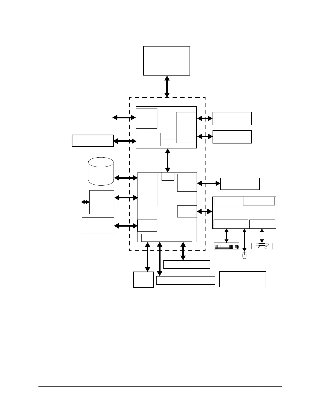
Figure 2-13. System Architecture, Block diagram
Parallel I/F [4]
Pentium
Processor
Q965 Chipset
Q965
82801
GMCH
SDRAM
Cntlr
PCIe
PEG I/F [1]
PCI Express
ICH8-DO
SATA
I/F
USB
I/F
Ch A DDR2
SDRAM
Ch B DDR2
SDRAM
SCH5317
I/O Cntlr.
Graphics
Cntlr.
RGB
Monitor
Hard Drive
USB Ports 1-8
Serial I/F [4]
Diskette I/F
Kybd-Mouse I/F
x16 slot (PEG)[1]
PCI Express x1 slot
SATA
HD Audio
Subsystem
Optical
PCI 2.3 slot(s) [3]
Keyboard
NIC
I/F
Mouse
Floppy
Audio I/F
LPC I/F
PCI Cntlr.
DMI
DMI
Power Supply
Notes:
[1] USDT: reverse-layout ADD2 card or PCIe x16 graphics card (with PCIe riser card installed).
[4] Requires optional cable assembly for USDT form factor, standard on SFF, ST, MT, and CMT form factors.
CMT: normal-layout graphics, ADD2, SDVO card.
SFF/ST: reverse layout graphics, ADD2, SDVO card.
[3] USDT requires PCI riser card
SATA-
-to
-PATA
Bridge [2]
[2] USDT only
Drive
Integrated