2-21
Installing the Switch
Installation Procedures
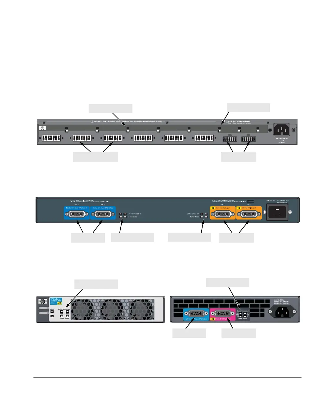
External Power Supply LEDs
The external power supply LEDs are duplicated on the front and back of the
units. The following graphics show examples of the back of the 600 EPS/RPS
and the front and back of the 630 RPS/EPS. There are dual colored (green/
orange) LEDs for each RPS and EPS port:
■ Device Connected
■ Power Status
Figure 2-12. Back of the 600 RPS/EPS
Figure 2-13. Back of the 620 RPS/EPS
Figure 2-14. Front and back of the 630 RPS/EPS
EPS 1
RPS 5
R5
RPS 3
R3R1
Power Status
RPS 1
R2
RPS 2
RPS 4
R4
R6
RPS 6
E1
E2
EPS 2
Device
Connected
Pow er
Status
Device Connected
RPS ports
EPS ports
RPS port LEDs
EPS port LEDs
EPS ports
RPS ports
EPS port LEDs
RPS port LEDs
EPS ports
RPS port LEDs
RPS/EPS port LEDs
RPS ports