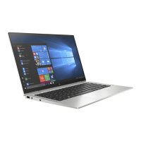
4. Remove the fan/heat sink assembly (4) from the system board (2).
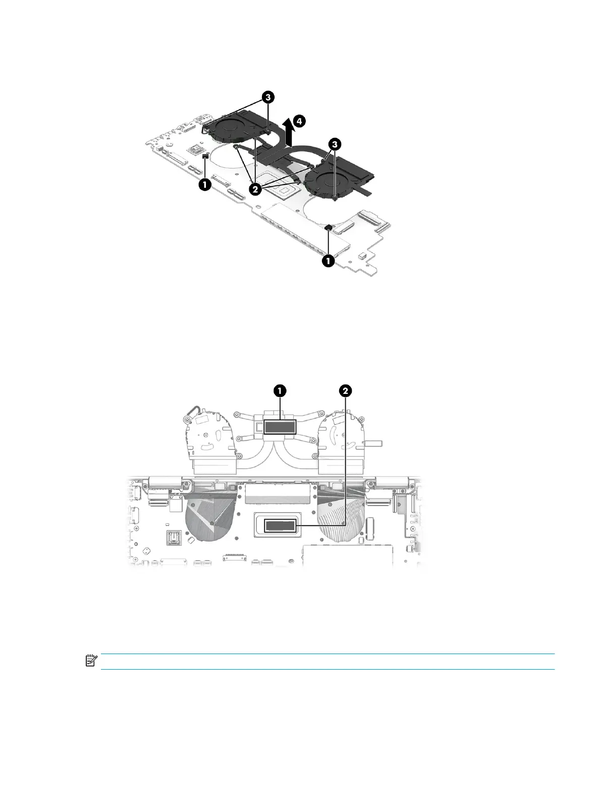
5. Thoroughly clean the thermal material from the surfaces of the fan/heat sink assembly and the system
board components each time the fan/heat sink assembly is removed. Replacement thermal material is
included with the fan/heat sink assembly and system board spare part kits. The following illustration
shows the replacement thermal material locations.
Thermal paste is used on the processor (1) and on the fan/heat sink assembly area (2) that services it.
Reverse this procedure to install the fan/heat sink assembly.
Sensor board cable
To remove the sensor board cable, use this procedure and illustration.
NOTE: The sensor board cable is available in the Cable Kit, spare part number M20835-001.
Before removing the sensor board cable, follow these steps:
ENWW Component replacement procedures 63
 Loading...