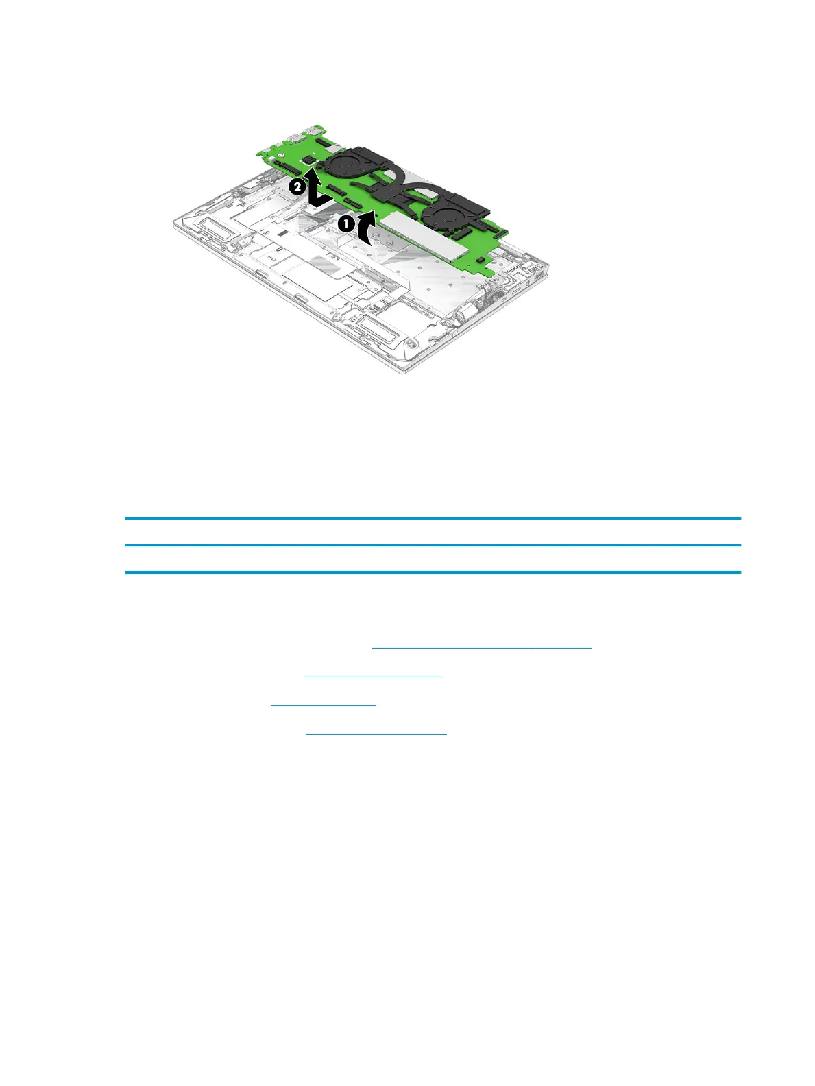
7. Remove the system board (2) by sliding it up and forward at an angle.
Reverse this procedure to install the system board.
Fan/heat sink assembly
To remove the fan/heat sink assembly, use these procedures and illustrations.
Table
5-11 Fan/heat sink assembly descriptions and part number
Description Spare part number
Fan/heat sink assembly assembly (includes replacement thermal material and fan cables) M16051-001
Before removing the fan/heat sink assembly, follow these steps:
1. Prepare the computer for disassembly (Preparation for disassembly on page 42).
2. Remove the bottom cover (Bottom cover on page 42).
3. Remove the battery (Battery on page 43).
4. Remove the system board (System board on page 58).
Remove the fan/heat sink assembly:
1. Disconnect the fan cables (1) from the system board.
2. In the order indicated on the fan/heat sink assembly, remove the four captive Phillips screws (2) that
secure the fan/heat sink assembly to the system board.
3. Loosen the four captive Phillips screws (3) that secure the fan/heat sink assembly to the system board.
62 Chapter 5 Removal and replacement procedures for authorized service provider parts ENWW
 Loading...