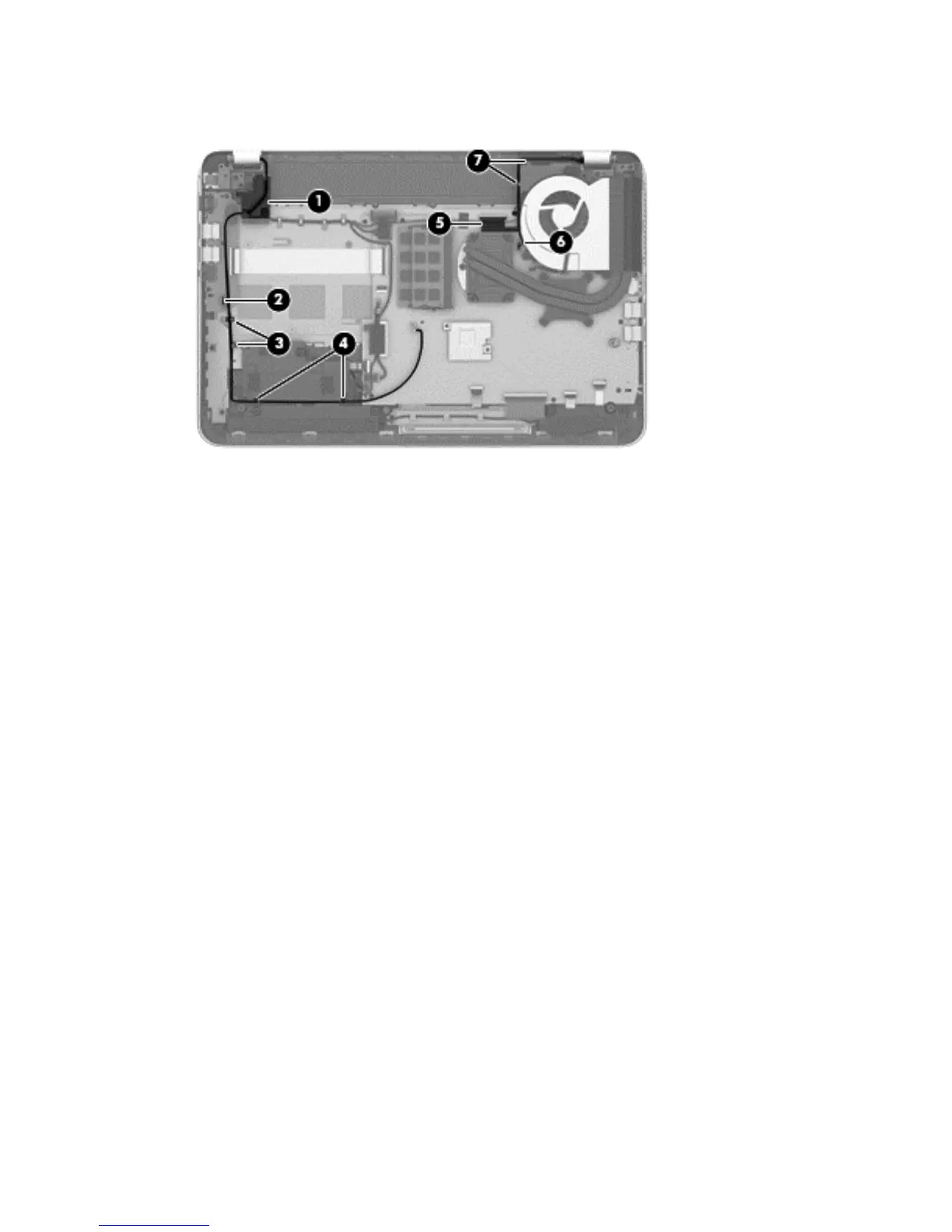
5. Release the display panel cable and the webcam/microphone module cable from the clips and routing
channel built into the right rear speaker (7).
6. Remove the three Phillips PM2.5×4.5 screws (1) (two on the left hinge, one on the right hinge) that
secure the display assembly to the top cover.
48 Chapter 6 Removal and replacement procedures for Authorized Service Provider parts
 Loading...