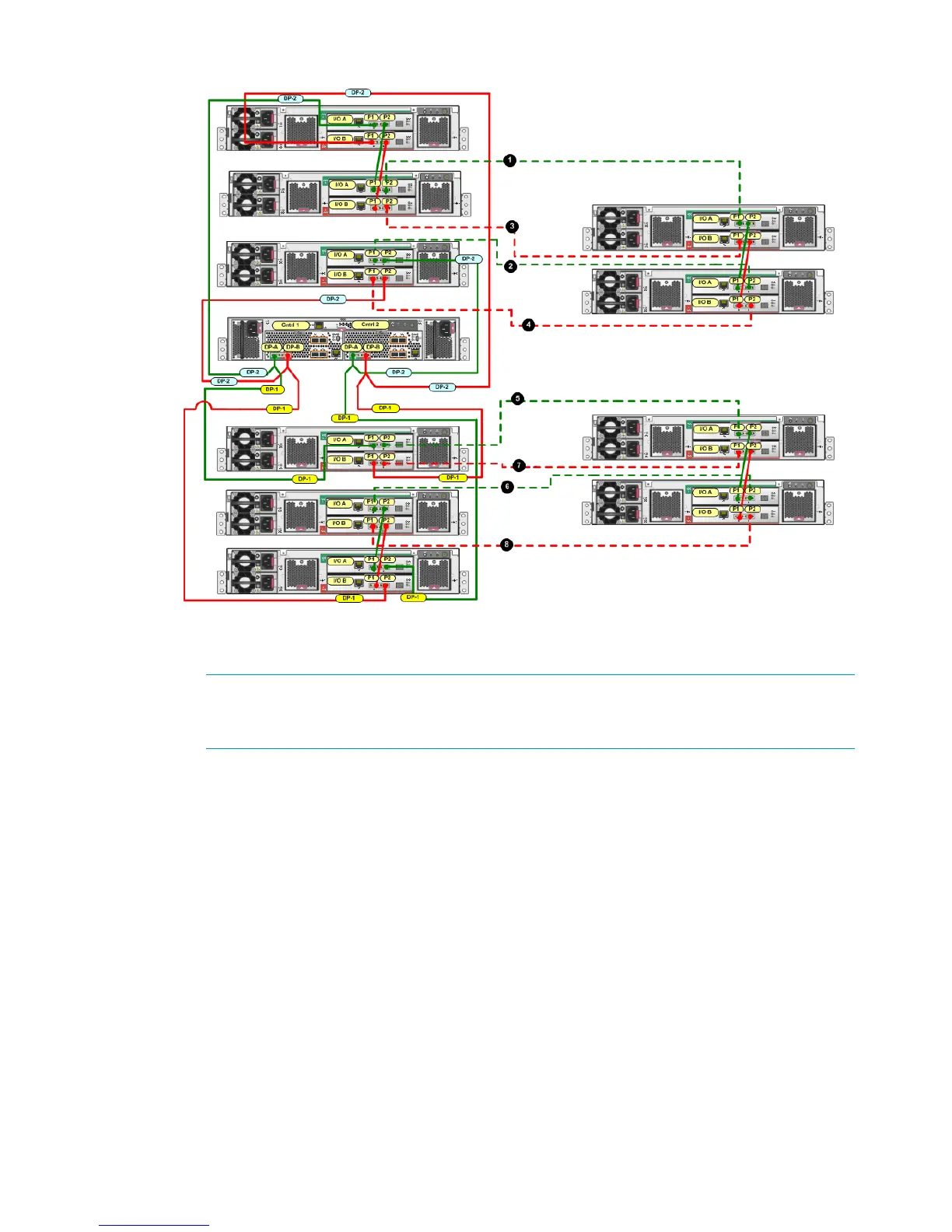
Figure 19 Complete cabling for a P6500 EVA 2C6D to 0C4D expansion
a. Remove the cable between P2 (I/O-A) on the middle disk enclosure and P1 (I/O-A) on
the bottom disk enclosure.
NOTE: You can break the connection between any disk enclosures in the main rack
except for disk enclosures that are connected to the controllers. The break described in
Step 2 and shown in the completed cabling (Figure 19 (page 26)) is just one example.
b. Using one of the 6m cables from the expansion kit, connect P2 (I/O-A) on the middle
disk enclosure in the main rack to P1 (I/O-A) on the top disk enclosure (first domain) in
the expansion rack (1, Figure 19).
c. Using one of the 6m cables from the expansion kit, connect P1 (I/O-A) on the bottom
disk enclosure in the main rack to P2 (I/O-A) on the bottom disk enclosure (first domain)
in the expansion rack (2, Figure 19).
d. Remove the cable between P2 (I/O-B) on the middle disk enclosure and P1 (I/O-B) on
the bottom disk enclosure.
e. Using one of the 6m cables from the expansion kit, connect P2 (I/O-B) on the middle disk
enclosure in the main rack to P1 (I/O-B) on the top disk enclosure (first domain) in the
expansion rack (3, Figure 19).
f. Using one of the 6m cables from the expansion kit, connect P1 (I/O-B) on the bottom disk
enclosure in the main rack to P2 (I/O-B) on the bottom disk enclosure (first domain) in
the expansion rack (4, Figure 19).
3. In the group of disk enclosures below the controller enclosure:
a. Remove the cable between P2 (I/O-A) on the top disk enclosure and P1 (I/O-A) on the
middle disk enclosure.
26 Connecting the main rack to the expansion rack

 Loading...