6. Repeat Step 5 for the other disk enclosures in the expansion rack. Visually check that each
disk enclosure powers on without errors. Wait at least one minute after all the enclosures are
powered on for the drives to spin up and stabilize. See “Verifying power up of expansion
rack” (page 27) for additional verification steps.
7. Continue with “Powering up the storage system (main rack)” (page 30) to power on the main
rack and complete verification of the newly added disk enclosures.
Connecting a P6500 EVA storage-centric rack to a 0C4D expansion rack
See Figure 13 (page 18) for a fully cabled P6500 EVA 2C6D configuration. In a 2C6D
configuration, the disk enclosures are balanced evenly into two groups—one group of three disk
enclosures above the controller enclosure and one group of three disk enclosures below the controller
enclosure.
NOTE: Although there is no stringent requirement that the number of disk enclosures be balanced
above and below the controller enclosure, HP strongly suggests that the number of disk enclosures
be split as evenly as possible.
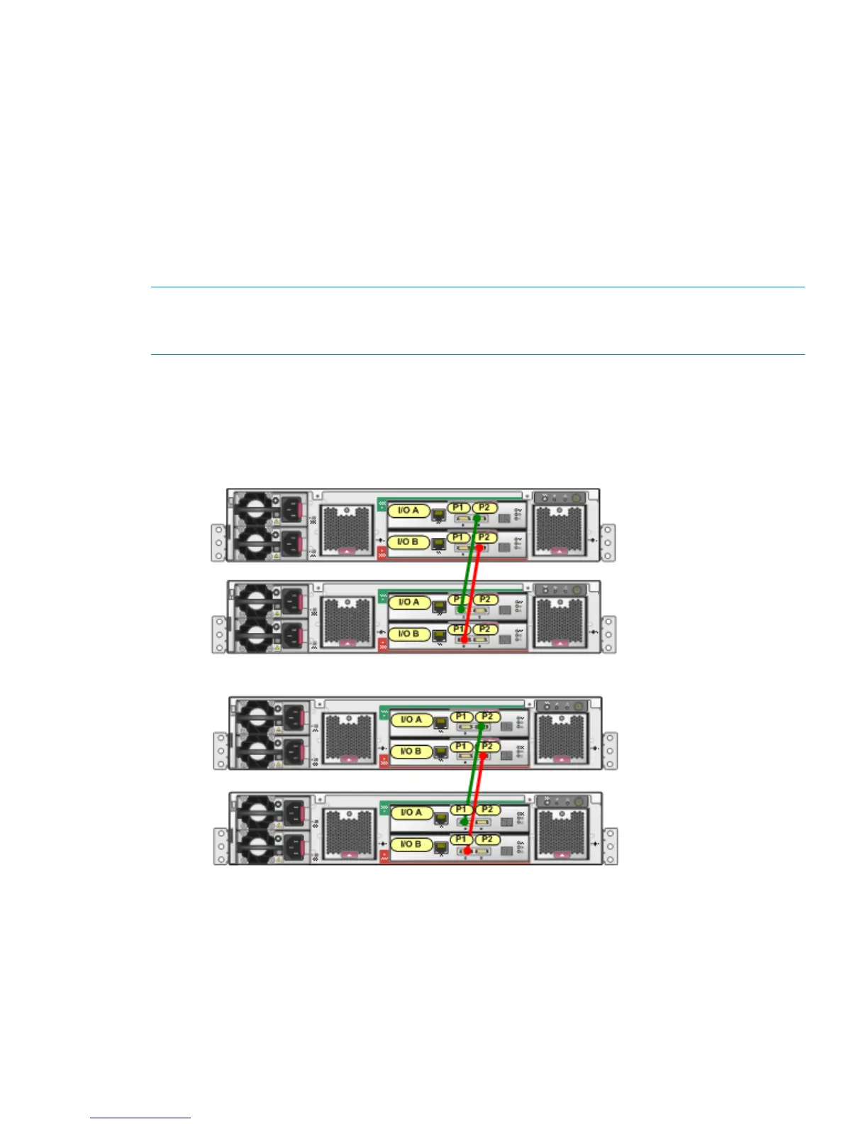
1. In the expansion rack, divide the disk enclosures into two groups—the top two disk enclosures
are in one group (first domain), the bottom two disk enclosures are in another group (second
domain). Connect the disk enclosures as shown in Figure 18 (page 25).
Figure 18 Connecting expansion rack disk enclosures for a P6500 EVA expansion
2. Figure 19 (page 26) shows the completed cabling from a P6500 EVA 2C6D main rack to a
0C4D expansion rack. In the group of disk enclosures above the controller enclosure in the
main rack:
Offline expansion 25

 Loading...