2. In the main rack:
a. Remove the cable between P2 (I/O-A) in the last disk enclosure in the top group and P1
(I/O-A) on the first disk enclosure in the bottom group.
b. Remove the cable between P2 (I/O-B) in the last disk enclosure in the top group and P1
(I/O-B) on the first disk enclosure in the bottom group.
NOTE: You can break the connection between any disk enclosures in the main rack except
for disk enclosures that are connected to the controllers. The break described in Step 2 and
shown in the completed cabling (Figure 17 (page 24)) is just one example.
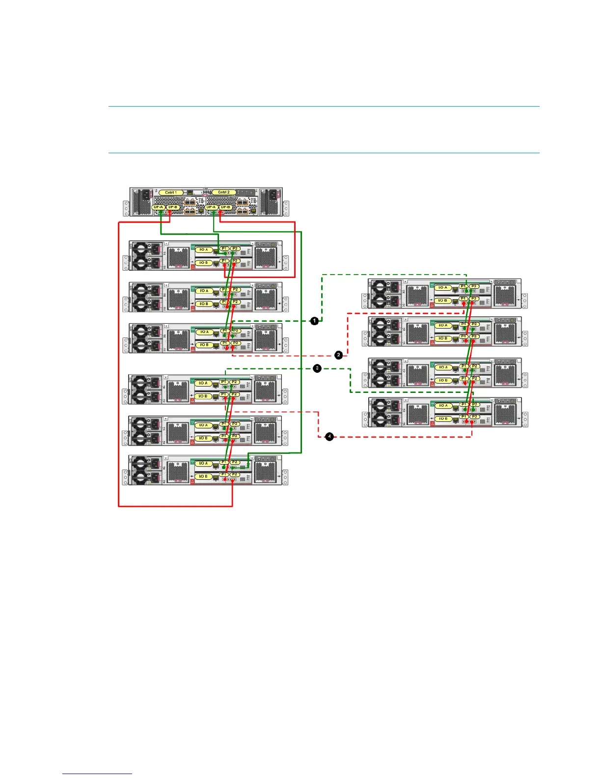
Figure 17 Complete cabling for a P6300 EVA 2C6D to 0C4D expansion
3. Use one of the 6m cables from the expansion kit for each of the following connections:
a. Connect P2 (I/O-A) on the disk enclosure in the top group in the main rack to P1 (I/O-A)
on the top disk enclosure in the expansion rack (1, Figure 17).
b. Connect P1 (I/O-A) on the disk enclosure in the bottom group in the main rack to P2
(I/O-A) on the bottom disk enclosure in the expansion rack (3, Figure 17).
c. Connect P2 (I/O-B) on the disk enclosure in the top group in the main rack to P1 (I/O-B)
on the top disk enclosure in the expansion rack (2, Figure 17).
d. Connect P1 (I/O-B) on the disk enclosure in the bottom group in the main rack to P2
(I/O-B) on the bottom disk enclosure in the expansion rack (4, Figure 17).
4. When the expansion rack is shipped, power cords should be connected to each disk enclosure
power supply. After completing the disk enclosure connections between the main rack and
expansion rack, connect the power cords from the expansion rack disk enclosures to a rack
power distribution module on the expansion rack.
5. On one expansion rack disk enclosure, press and hold the Power On/Standby button on the
power UID bezel (located at the rear of the disk enclosure) to power on the disk enclosure.
24 Connecting the main rack to the expansion rack

 Loading...