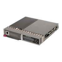
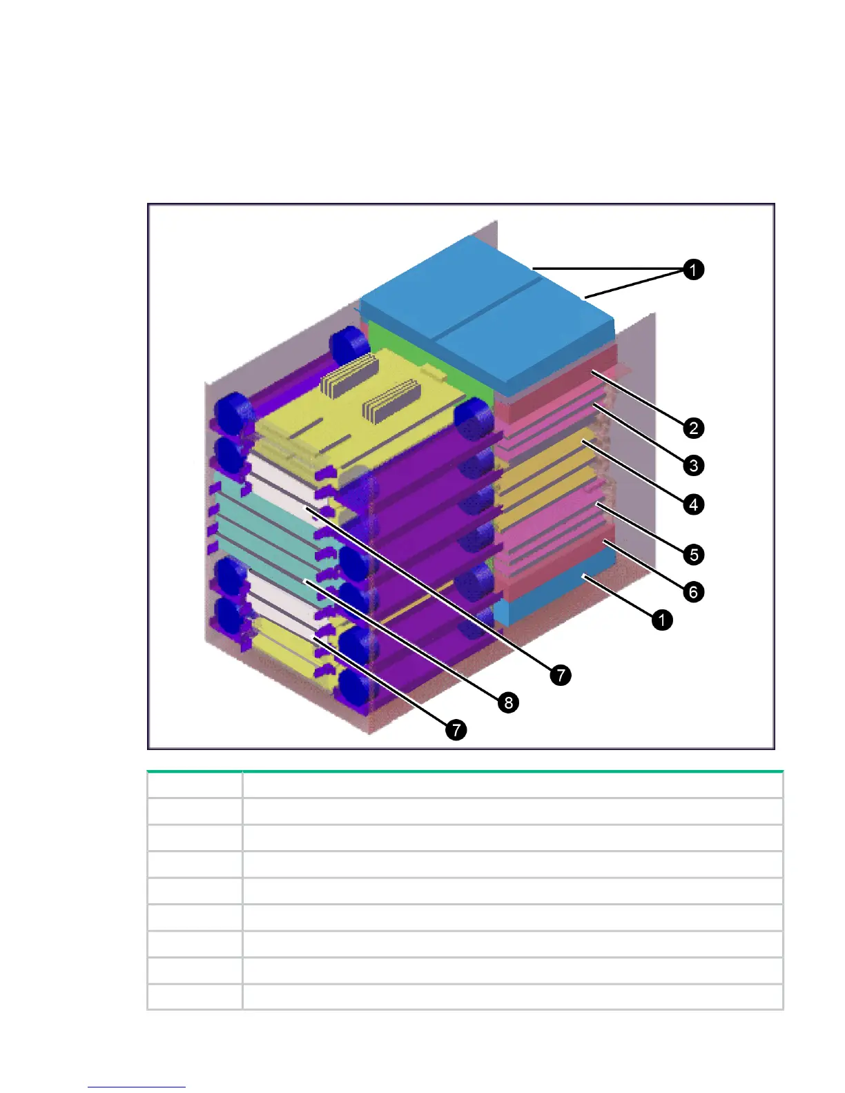
The controller chassis includes the following maximum number of components: two service
processors, 512 GB cache memory, four grid switches, four redundant power supplies, eight
channel adapters, four disk adapters, and ten dual fan assemblies. It is mounted at the bottom
of the rack because it is the heavier of the two units. If a system has two SVPs, both SVPs are
mounted in controller chassis #0.
The following illustration shows the locations of the components in the controller chassis.
Figure 2 Controller chassis
DescriptionItem
AC/DC: Power Supply 2 or 4 per controller1
Service Processor: One or two units in the #0 controller chassis2
CHA3
Grid switches4
CHA (up to 7) and DKA (up to 4)5
Service Processor: One or two units in the #0 controller chassis6
Cache: 2 to 8 cache boards in pairs (2, 4, 6, 8)7
P9500: 2 to 4 microprocessor boards8
Hardware overview 7
 Loading...