Pulley replacement only for presses operating at 60Hz frequency
Proprietary and Confidential MKT-0102-AI Rev 00 Page 6 of 10
3. Mount the new outer pulley on the shaft. See Figure 4.
4. Align the new inner pulley with the dowel. See Figure 4.
Mount it on the shaft.
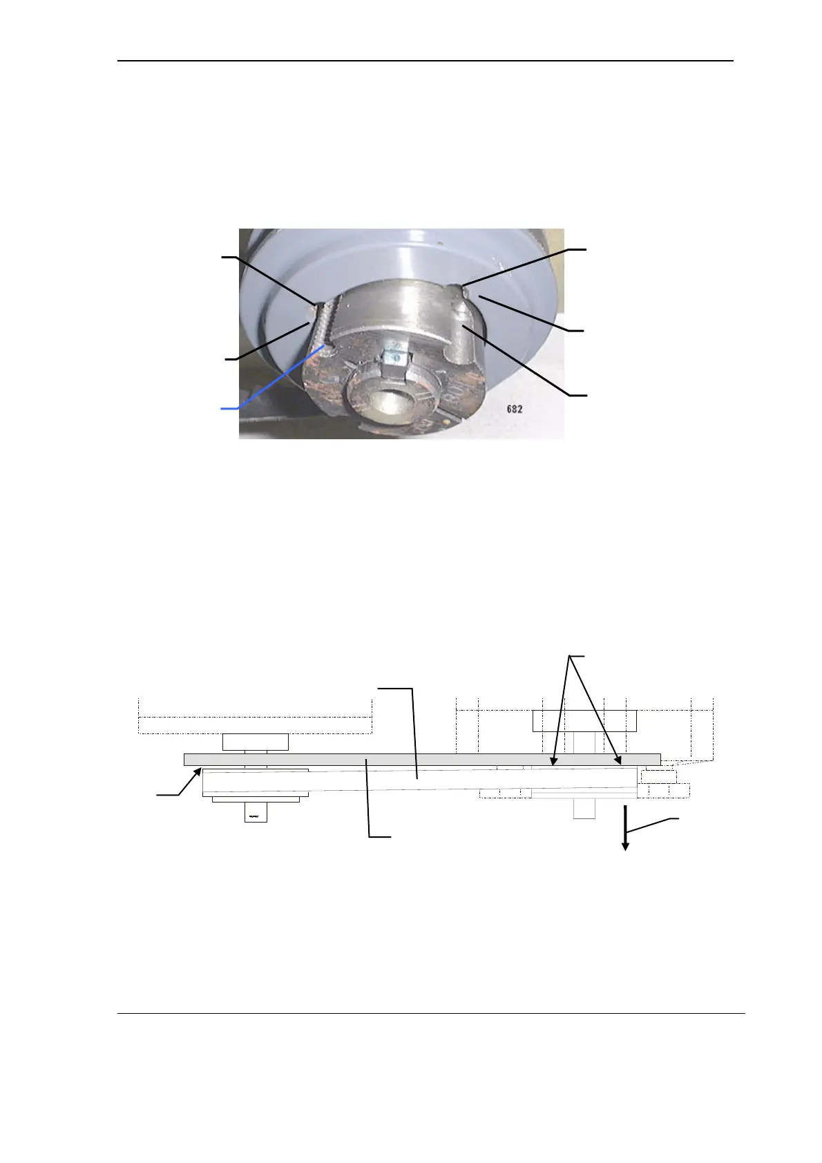
5. Fit the outer pulley over the inner pulley. See Figure 5.
Ensure that their relative positions are correct.
Figure 5 Positioning of the outer pulley relative to the inner pulley
The non-threaded half-hole on the outer pulley must be positioned opposite
the threaded half-hole on the inner pulley. These two half-holes form the
extraction hole. See Figure 5.
6. Insert the two inset M6 Allen screws. Do not tighten the screws at this stage.
7. Remount the belt on both the pump and motor pulleys.
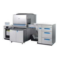
8. Align the pump pulley with the motor pulley as follows:
a. Hold a straight-edge flat against the back surface of the pump pulley.
See Figure 6.
Figure 6 Placement of the straight edge
b. Slide the pulley along its shaft until the straight-edge touches the
motor pulley. See Figure 6 and Figure 7.
INSET SCREW HOLE
(2 PLACES)
EXTRACTION
HOLE
NON-THREADED
HALF-HOLE
THREADED
HALF-HOLE
THREADED
HALF-HOLE
NON-THREADED
HALF-HOLE
SLIDE PULLEY
WITH STRAIGHT
EDGE ALONG
SHAFT
FLAT AGAINST
BACK SURFACE
STRAIGHT EDGE
NOT TOUCHING
MOTOR PULLEY
PUMP
PULLEY
MOTOR
PULLEY
STRAIGHT EDGE
BELT