2-11
Installing the Switch
Installation Procedures
Installing the Switch
When the self test completes successfully:
•The Power and Fan Status LEDs remain on.
•The Fault and Self Test LEDs go off.
• The port LEDs on the front of the switch go into their normal opera-
tional mode:
– If the ports are connected to active network devices, the LEDs
behave according to the Port LED View or LED Mode selected.
For the non-PWR switches, in the default view mode (Link), the
LEDs should be on. For the PWR switches, with two LEDs per
connections, the Link LEDs will be on and the Mode LEDs will
flicker if there is network activity.
– If the ports are not connected to active network devices, the Link
and Activity LEDs will stay off.
If the LED display is different than what is described above, especially if
the Fault and Self Test LEDs stay on for more than 60 seconds or they start
blinking, the self test has not completed correctly. Refer to chapter 4,
“Troubleshooting” for diagnostic help.
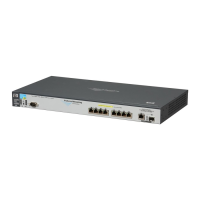
4. Mount the Switch
After the switch passes self test, it is ready to be mounted in a stable location.
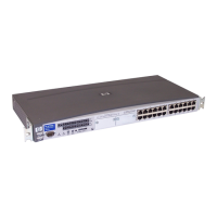
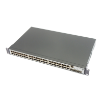
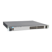
The Series 2600 Switches can be mounted in these ways:
1
The 2600-8-PWR switch can be wall mounted. See page 2-18 for instructions.
Rack or Cabinet Mounting
The Series 2600 Switches are designed to be mounted in any EIA-standard 19-
inch telco rack or communication equipment cabinet. Note that the mounting
brackets have multiple mounting holes and can be rotated allowing for a wide
variety of mounting options. Secure the rack in accordance with the
manufacture’s safety guidelines.
WARNING For safe operation, please read the mounting precautions on
page 2-4, before mounting a switch.
Mounting Location Non-PWR Switches PWR Switches
In a rack or cabinet Yes Yes
On a horizontal surface Yes Yes
On a wall Yes No
1