2-37
Installing the Switch
Sample Network Topologies for PWR Switches
Installing the Switch
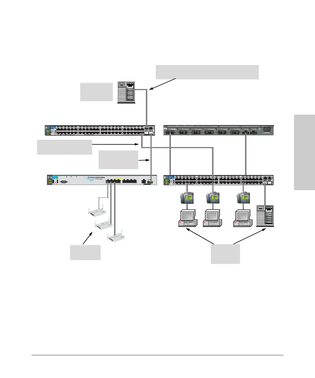
As a Segment Switch Implementing PoE
As shown in the illustration above, the IP telephones have been inserted in
between the Switch 2650-PWR and the PCs, and a WAP has been connected
to the Switch 2650-PWR. Both the telephones and WAP will receive PoE power
from the Switch 2650-PWR. Only devices directly connected to the PWR
switches can receive PoE power if they are 802.3af compliant, except on the
Switch 2600-8-PWR, it has the ability to supply power to pre-802.3af-standard
devices, such as legacy (or non-standard) IP phones. Devices connected to a
non-PWR segment switch cannot receive PoE power.
PoE
Power
Fault
Dual-Personality P ort:
10/1 00/1 000-T (T) o r Mini-GBIC (M)
(Port 9T is IEEE A uto MDI/MDIX)
Status
Reset Clear
Console
PoE-Integrated 10/100-TX P orts (1 - 8)
—(Ports are HP Aut o-MDIX)
ProCurve
Switch 2600-PWR
J8762A
*
Spdmode: off = 10Mbps, flash = 100 Mbps, on = 1000 Mbps
Link
Mode
LED
Mode
Spd
Act
FDx
Test
EPS
Fan
234
Link Mode
1
Link
Mode
5 6
7
8
9T
Link
Mode
PoE
*
9M
!
Useonly one (T or M) for P ort 9
RPS
Server with
Gigabit
Ethernet NIC
Switch 2650 Non-PWR
Category 5e twisted-pair straight-through or
crossover cable for 1000 Mbps connection to server
Gigabit
fiber-optic cable
uplink
Switch 2600-8-PWR
600 RPS/EPS
PCs, printers,
and local
servers
Wireless
Access Points
Switch
2650-PWR
Twisted-pair straight-
through or crossover cables