2-27
Installing the Switch
Installation Procedures
Installing the Switch
610 EPS LEDs
For a complete description of the LEDs see the documentation that came with
the 610 EPS.
Operating Characteristics of the 610 EPS (J8169A)
The 610 EPS does not have any RPS ports and can not supply RPS power. It
has four EPS Ports. Two in Pair A and two in Pair B. Each pair can provide a
maximum of 408 watts of PoE power to a switch. Again, it is important to
understand the PoE power requirements of the switches. For further
information regarding the 610 EPS PoE capabilities, see the PoE Planning
and Implementation Guide, which is on the Documentation CD-ROM that
came with your switch and the documentation that came with the 610 EPS.
For redundant or additional PoE power, connect the 610 EPS to the switch
using one of the four supplied EPS cables. EPS cables are 2.00 meters (6.56
feet) in length.
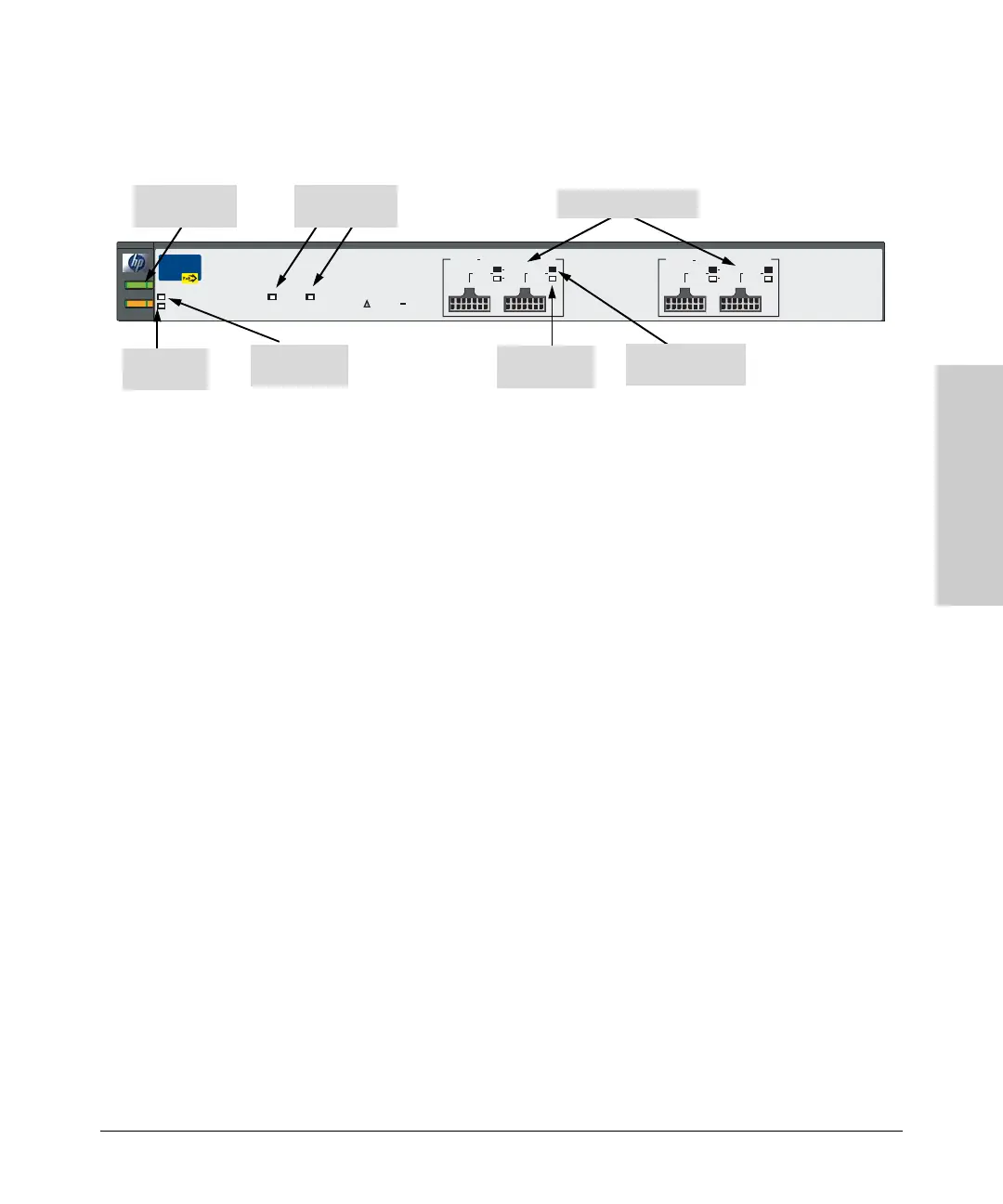
The following illustration demonstrates and example of connectivity between
a 610 EPS device and two Switch devices as a PoE power supply.
Power
Fault
hp procurve
610 eps
J8169A
Fan/Temp Status flash = Temperature too high
Fan/Temp Status + Fault flash = Fan failure
Fan/Temp Status
Internal Power Status
In Ready
Out Ready
Backup Power Ports Status
EPS Ports Pair A
(
408 W total for PoE applications
)
EPS Ports: 50V 8.3A max each.
EPS A1
Power
Status
A2
B1
B2
A1
Device
Connected
EPS A2 EPS B1
Power
Status
Device
Connected
EPS B2
EPS Ports Pair B
(
408 W total for PoE applications
)
Power and
Fault LEDs
610 EPS
Interna l Power
Status LED
Fan/Temp
Status LED
Backup Power
Port LEDs
EPS Port LEDs
Device Connected
LED
Power Status
LED