17
IMPORTANT:
• Repair Condition: Connector repair is only for out of warranty.
• Repairing must operate by professional repairers (Note) in repair center, not applicable for end
user.
• Electrostatic protection is required when component replacement is required.
• The monitor meets ROHS, please use Lead-free solder wire for soldering.
• If Connector need to replace, must check specification and part number whether match the BOM
and location.
• If connector need to replace, please insert new parts carefully because the near pin may cause
short circuit by inappropriate operate.
• DO NOT allow any liquid on the board. Water and moisture may cause short-circuit to the
electronic components and lead to malfunctions.
• The fusion point of Lead-Free solder is requested. Repairing with conventional lead wire may
cause damage.
• Work quickly to avoid overheating the circuit board as soon as you confirm the steady soldering
condition.
• Keep the soldering iron tip clean and well tinned and when replacing parts.
• A close inspection of the circuit board revealed look in good condition.
• After repaired, must connect source to each port to check Main board function is ordinary.
Note: (The requirement of professional repairers’ regulation by ERP lot5)
1) The professional repairer has the technical competence to repair electronic displays and complies
with the applicable regulations for repairers of electrical equipment in the Member States where it
operates. Reference to an official registration system as professional repairer, where such system
exists in the Member States concerned, shall be accepted as proof of compliance with this point.
2) The professional repairer is covered by insurance covering liabilities resulting from its activity,
regardless of whether this is required by the Member State.
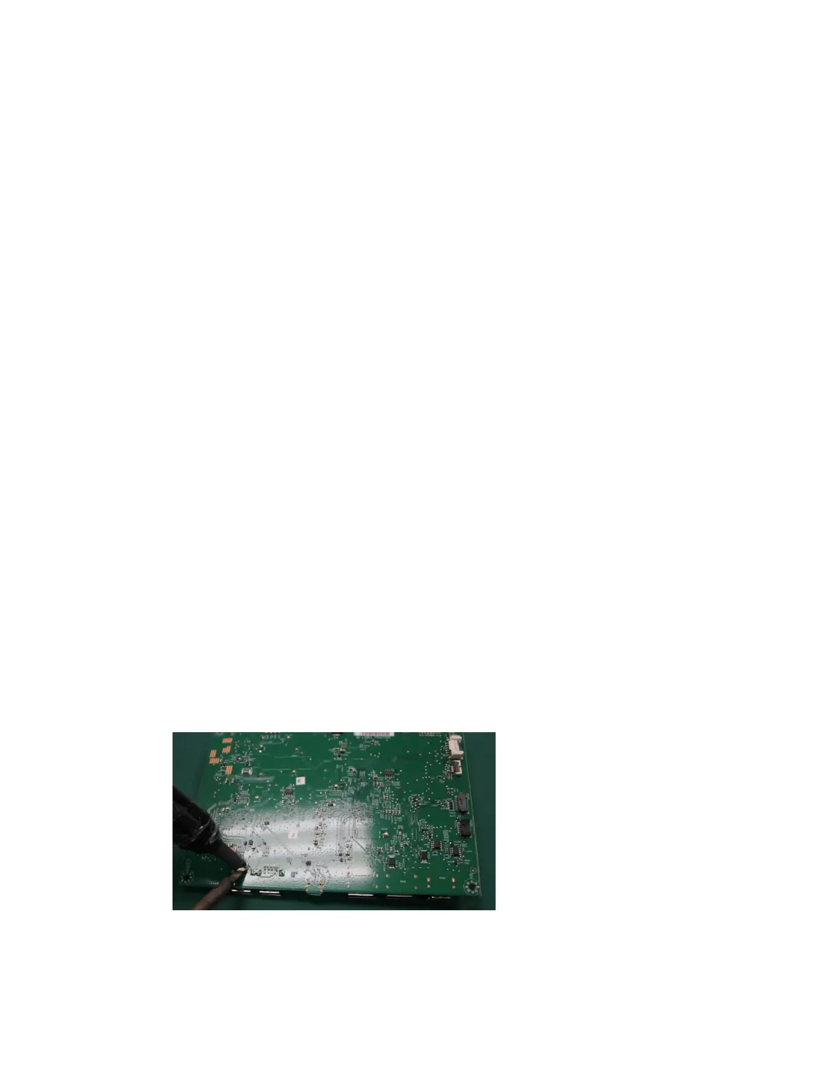
Audio connector CN605
Repair the audio connector:
1) Use a hot air gun to melt the solder on the pins. Pin solder with soldering iron and absorber. You
can gently push down with the soldering iron once everything is molten to move the CN605 out of
the through holes.
2) Lift the CN605 connector from the circuit board.
3) Place the new component on the circuit board. Be sure that it matches the footprint.
4) Solder the new component.
 Loading...