Expansion connector board
Description
HDMI expansion connector board
Serial port expansion connector board
DisplayPort expansion connector board
An expansion board can be installed near the back of the system board that provides an additional connector
on the rear I/O panel. The board is secured with two screws and connects to the a connector on the system
board.
To remove the expansion connector board:
1. Prepare the computer for disassembly (Preparation for disassembly on page 20).
2. Remove the top cover (Top cover on page 21).
3. Remove the heat sink (Heat sink on page 43).
4. Remove the fan (Fan on page 37).
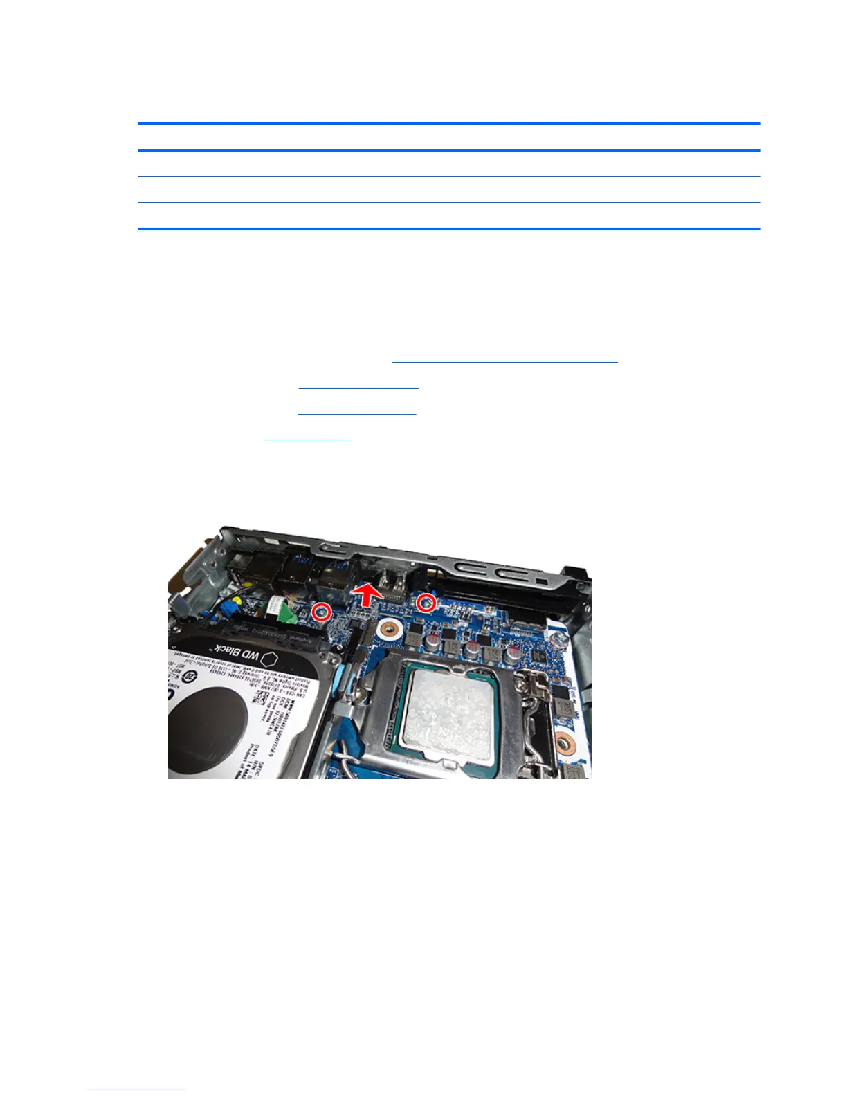
5. Remove the two Phillips screws that secure the board to the system board.
6. Lift to disengage the board from the system board connector, and then remove the expansion connector
board from the computer.
To install the expansion connector board, reverse the removal procedures.
48 Chapter 4 Removal and replacement procedures – desktop mini (DM) chassis
 Loading...