1 Preparing for installation
Package contents
• One AP
• One weatherproof RJ-45 Ethernet connector
• One pole mounting/wall mounting bracket
• Bracket bolts (x2), lock washers (x2), flat washers (x4)
• Wall anchors (x4) and screws (x4)
• Pole clamps (x2) for a 5 cm (2 inch) diameter pole
• Documentation
Additional equipment needed
In addition to the items supplied with the AP, protection equipment will be required according to
your electrical code. Consult the respective antenna guide (available online, search by antenna
part number), including the Lightning Arrester section for important safety information and
instructions. Note that although the AP includes a built-in Ethernet surge suppressor, you should
add an Ethernet surge suppressor where the Ethernet cable enters the building.
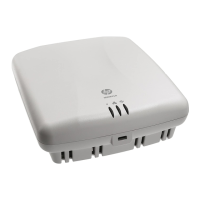
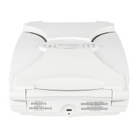
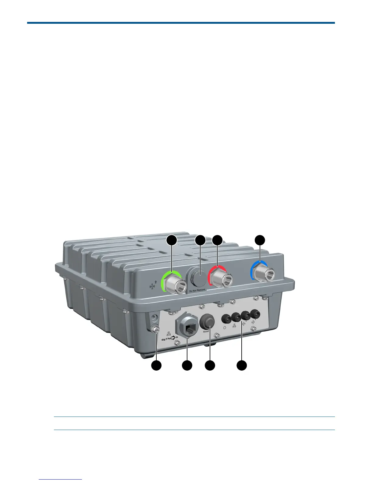
Identifying AP components
Figure 1 AP key components (bottom end)
4. Ethernet connector1. Radio 2 antenna connectors (x3)
5. Reset button2. Vent nut (do not remove)
6. Status LEDs (Power, Ethernet, Radio 1, Radio 2)3. Grounding lug with screw
NOTE: Three Radio 1 antenna connectors are on the top end of the AP.
4 Preparing for installation
 Loading...