2 Installing
WARNING! This is a general procedure. It is the installer’s responsibility to perform the installation
in accordance with local electrical code and regulations.
Planning the installation
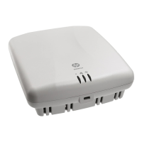
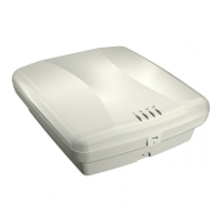
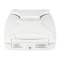
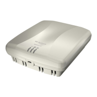
Identify a suitable installation location. The AP is IP67 and NEMA 4X rated, providing protection
against water intrusion and salt fog damage. Local electrical and building codes and regional
regulations will dictate many aspects of your installation. HP recommends that you test transmission
and reception at the proposed location before installing.
You must provide an effective earth ground for the AP. It is rarely sufficient to use a metal pole for
equipment grounding. To ensure safety and electrical protection, you must decide how to route
the Ethernet cable from the building to the AP.
Preparing the weatherproof Ethernet cable
To provide a weatherproof seal, the Ethernet port on the AP uses a custom weatherproof cable
connector (supplied). You must terminate your Ethernet cable with this connector as described in
the following procedure. Cable length must not exceed 100 meters (300 feet). Spare weatherproof
cable connectors are available from HP (5066-1705).
CAUTION: Ruggedized Ethernet cables must be used for outdoor cable runs.
NOTE: All image key references (numbers in parentheses) in this procedure reference Figure 2.
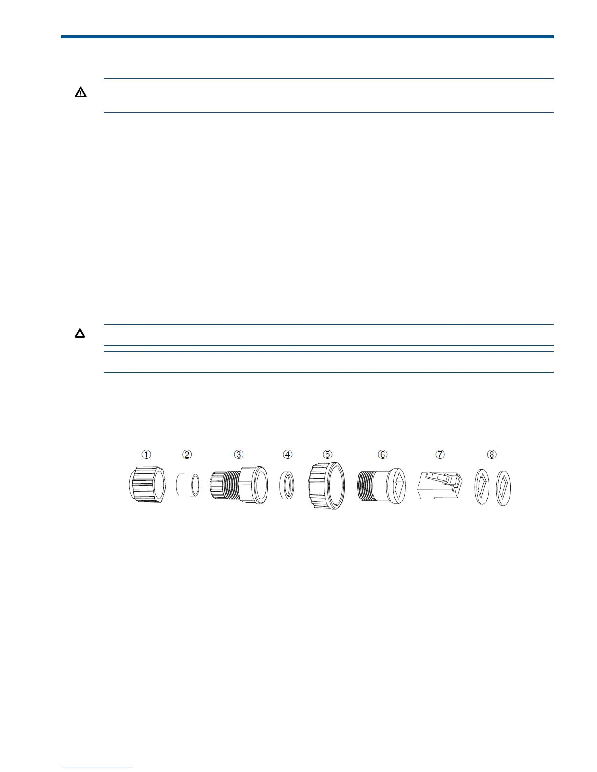
1. Carefully unpack the nine weatherproof connector items from the plastic bag, identifying all
parts as illustrated. If any parts are missing, DO NOT proceed. Contact support to request a
replacement parts kit.
Figure 2 Weatherproof connector parts
7. RJ-45 plug5. Screw nut3. Clamp ring1. Sealing nut
8. RJ-45 gaskets6. Body4. Gasket2. Seal
2. If your Ethernet cable already has an RJ-45 connector on the end that will connect to the AP,
remove the RJ-45 connector by cutting the cable at least 1.2 cm (.5 inch) before the RJ-45
connector. Be sure to make a clean cut with a pair of sharp angle cutters. The complete cut
(through both the cable sheath and all wires) must occur in a single cutting motion.
3. Hold the clamp ring (3) horizontally, with its fingers to the left. Insert the seal (2) into the fingers
on the left end so that it is flush with the end of the fingers. The gasket (4) is beveled on one
side. Insert the gasket (4) into the right end, beveled side facing to the left, pushing it against
the ridge at the end of the threads. The beveled side should face inwards away from the screw
nut (5).
4. Thread the sealing nut (1) onto the left end of the clamp ring (3). Tighten it only enough to
stay attached.
Planning the installation 7
 Loading...