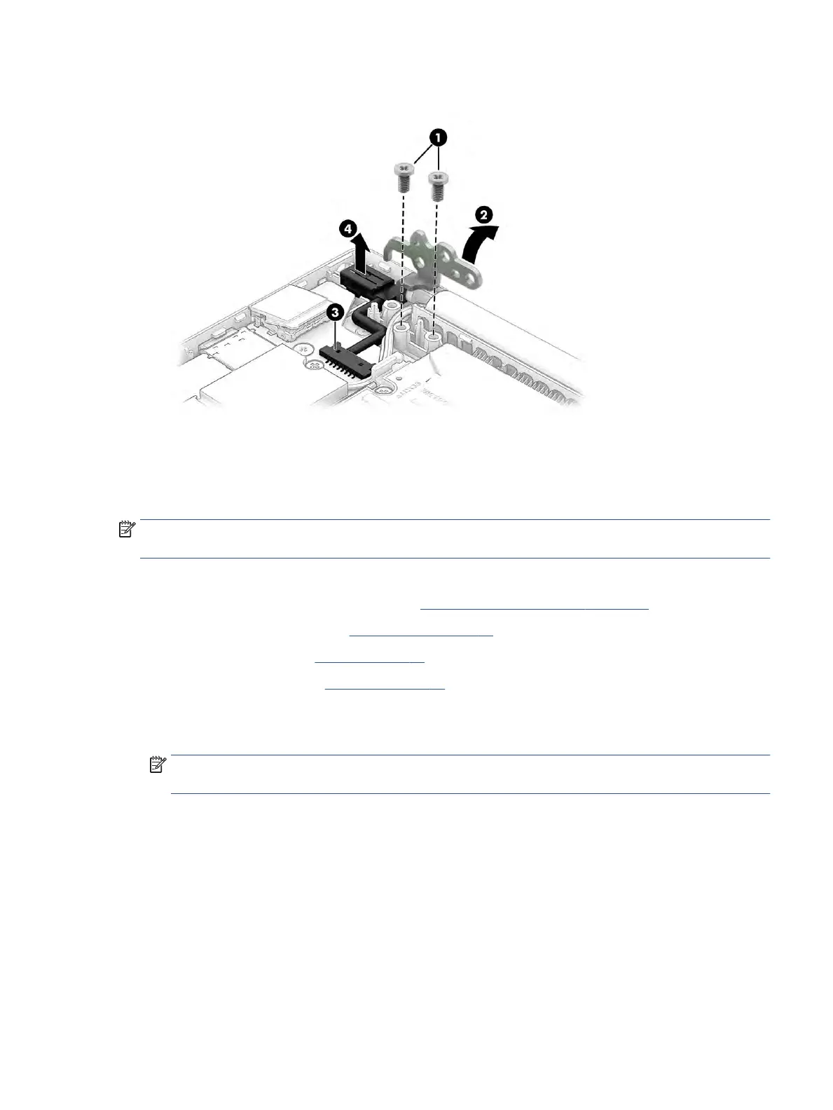
4. Remove the power connector cable from the computer (4).
Reverse this procedure to install the power connector cable.
Display assembly
To remove and disassemble the display assembly, use these procedures and illustrations.
NOTE: The display assembly is available as a spare part only at the subcomponent level. For display
assembly spare part information, see the individual removal subsections.
Before removing the display panel, follow these steps:
1. Prepare the computer for disassembly (see Preparation for disassembly on page 29).
2. Remove the bottom cover (see Bottom cover on page 29).
3. Remove the battery (see Battery on page 31).
4. Remove the heat sink (see Heat sink on page 38).
Remove the display assembly:
1. Disconnect the WLAN antenna cables (1) from the terminals on the WLAN module.
NOTE: The WLAN antenna cable labeled 1/MAIN connects to the WLAN module Main terminal. The
WLAN antenna cable labeled 2/AUX connects to the WLAN module Aux terminal.
2. Disconnect the camera cable from the system board ZIF connector (2).
Component replacement procedures 45
 Loading...