1-9
Introducing the Switch
Front of the Switch
Introducing the Switch
Expansion Module LEDs
“Expansion Module” LEDs refer to the LEDs specific to the expansion module.
These LEDs are located on the physical expansion module bulkhead. These
LEDs are only viewable in the rear of the Switch 3400cl-48G product on the
Expansion Slot Module itself.
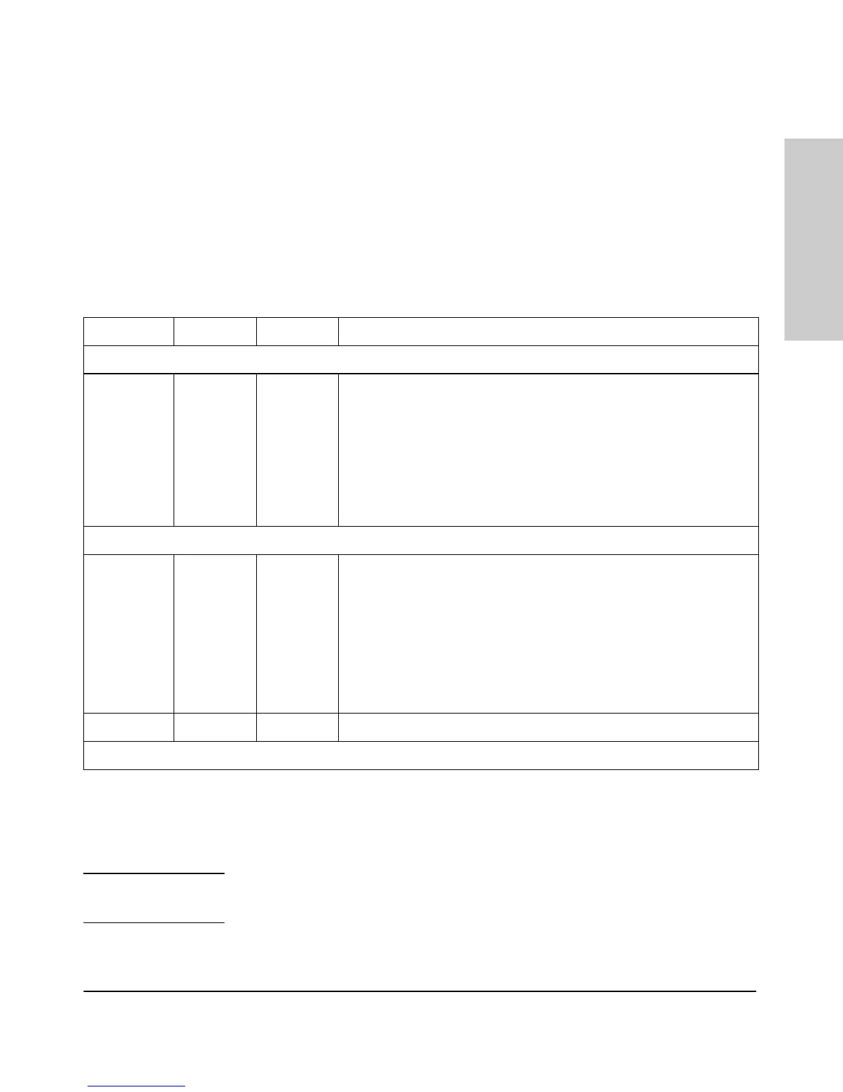
Table 1-3. Expansion Module LEDs
Expansion module LEDs for port A and B operate in modes for Link and
Activity. FDx and Spd modes have no meaning for the 10-GbE ports on the
expansion module.
Caution It is recommended the power to the switch be removed before inserting or
extracting the Expansion Module.
Name Color Mode Description
Expansion Module LEDs per module
Module
(Mdl) Power
(ports A & B)
Module
(Mdl) Fault
(ports A & B)
Green
Orange
On
Off
On
Expansion module is plugged into expansion slot and operating correctly
Expansion module's power has been turned OFF, and the card can be
removed from the box if necessary.
Expansion module is plugged into expansion slot but has experienced a
fault
Expansion Module LEDs per port
Link Green On
Off
Blinking
Indicates that the port LEDs are displaying link information:
• if the port LED is on, the port is enabled and receiving a link indication
from the connected device.
• if the port LED is off, the port has no active network cable connected,
or is not receiving link beat or sufficient light. Otherwise, the port may
have been disabled through the switch console, the web browser
interface, or ProCurve Manager.
• if the port LED is blinking* simultaneously with the Fault LED, the
corresponding port has failed its self test.
Act Green On Indicates the port LEDs are displaying network activity information.
* The blinking behavior is an on/off cycle once every 1.6 seconds, approximately.

 Loading...