EasyManuals Logo

HP ProCurve Series User Manual

HP ProCurve Series
110 pages
To Next Page IconTo Next Page
To Previous Page IconTo Previous Page
Page #62 background imageLoading...
Page #62 background image
4-2
Replacing Components
Replacing the fan tray
Replacing Components
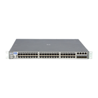
3. Remove the retaining screw securing the fan tray, disconnect the fan tray
cable connector, and lift the fan tray assembly out.
Figure 4-1. Fan tray retaining screw and cable.
4. Install the new fan tray assembly, reconnect the fan tray cable connector,
reinstall and tighten the retaining screw.
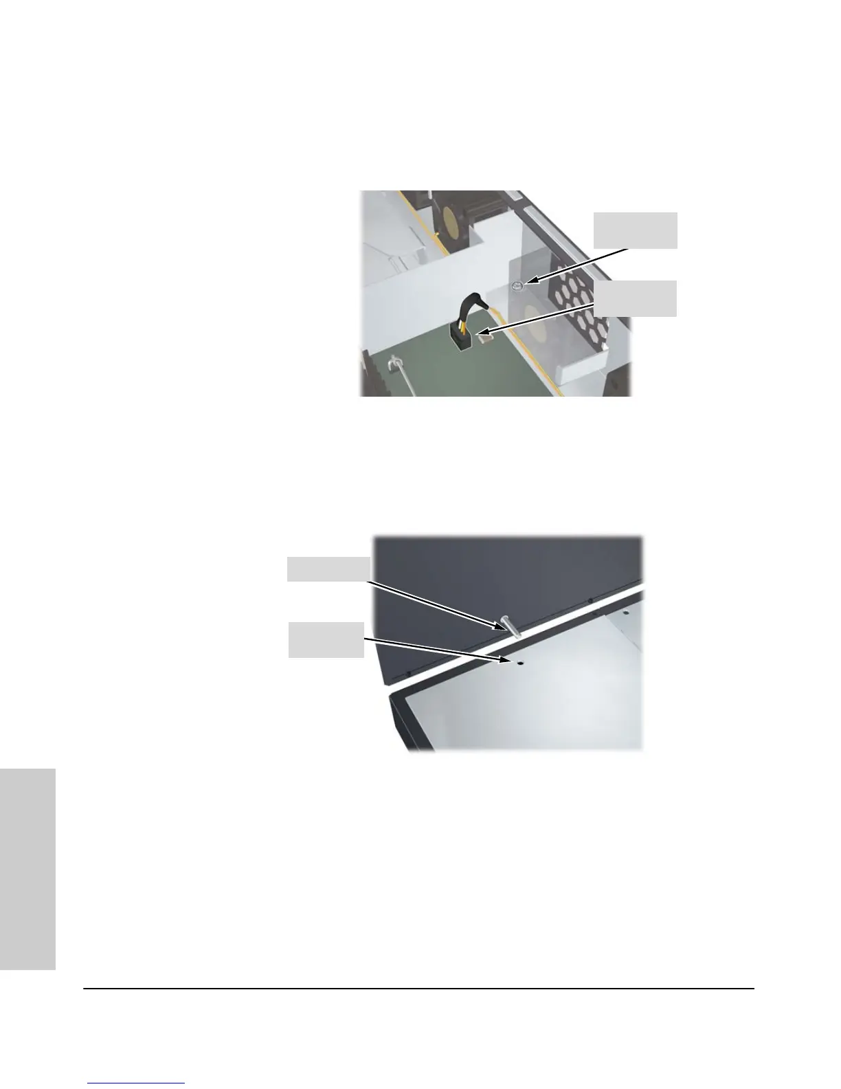
5. Reinstall the top of the switch. Align the top cover pin with the hole.
Figure 4-2. Alignment of the top cover pin with the alignment hole.
6. Reinstall and tighten all the screws securing the top.
7. Reconnect the power cable to the switch.
Retaining
Screw
Cable
Connector
Top Cover Pin
Alignment
Hole

Table of Contents

Other manuals for HP ProCurve Series

Questions and Answers:

Question and Answer IconNeed help?

Do you have a question about the HP ProCurve Series and is the answer not in the manual?

HP ProCurve Series Specifications

General IconGeneral
SeriesProCurve
CategorySwitch
PortsVaries by model
Port SpeedVaries by model
Switching CapacityVaries by model
Forwarding RateVaries by model
Power SupplyVaries by model
ManagementWeb, CLI, SNMP
VLAN SupportYes
LayerLayer 2 or Layer 3, varies by model
Jumbo Frame SupportYes
DimensionsVaries by model
WeightVaries by model

Related product manuals