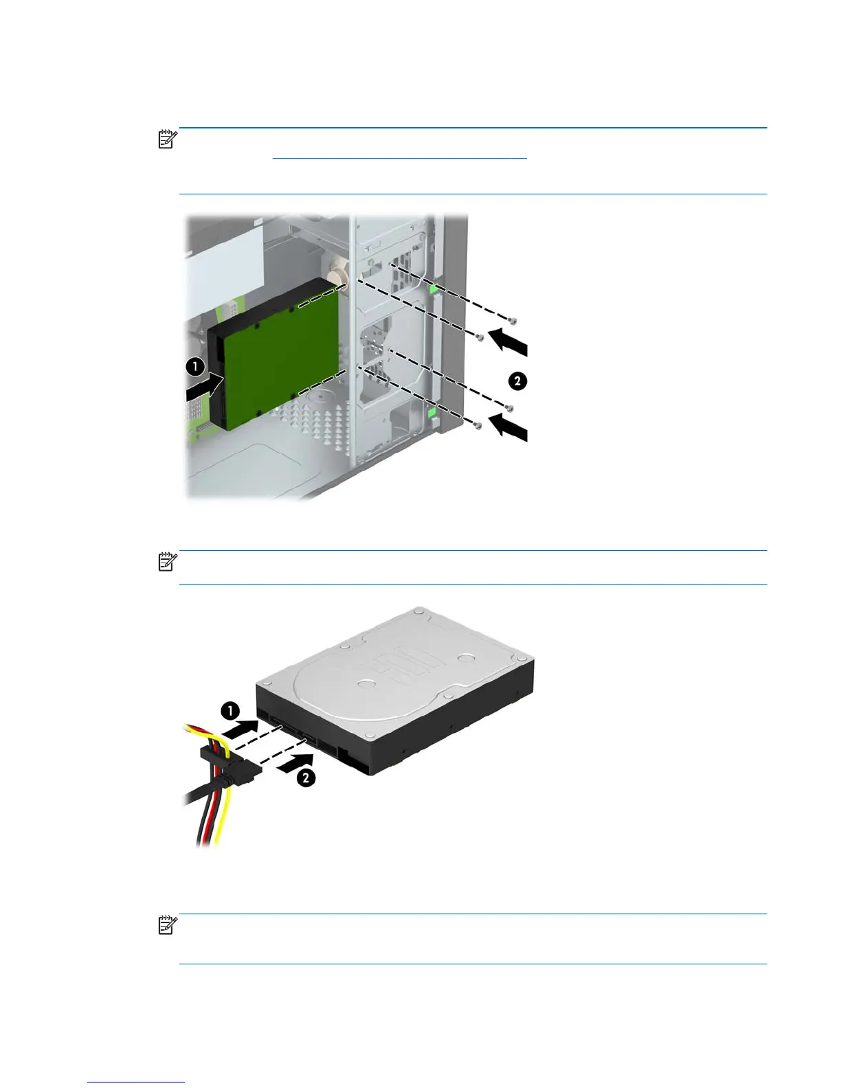
7. Slide the drive into the drive bay (1) and install the four 6-32 mounting screws (2) to secure the
drive in place.
NOTE: HP has supplied four extra 6-32 mounting screws on the front of the chassis behind the
bezel. Refer to
Installing and removing drives on page 21 for an illustration of the extra mounting
screws location. When replacing a hard drive, use the four 6-32 mounting screws that were
removed from the old drive to install the new one.
8. Connect the power cable (1) and data cable (2) to the back of the hard drive.
NOTE: The power cable for the hard drives is a two-headed cable that is routed from the
power supply to the rear of the hard drive bays.
9. If installing a new drive, connect the opposite end of the data cable to the appropriate system
board connector.
NOTE: You must connect the primary hard drive data cable to the dark blue connector labeled
SATA0 to avoid any hard drive performance problems. If you are adding a second hard drive,
connect the data cable to the light blue SATA connector labeled SATA1.
Installing and removing drives 31
 Loading...