Hardware options installation 36
10.
Connect the rest of the drive cables required in this drive configuration. For more information, see
"Storage cabling (on page 71)."
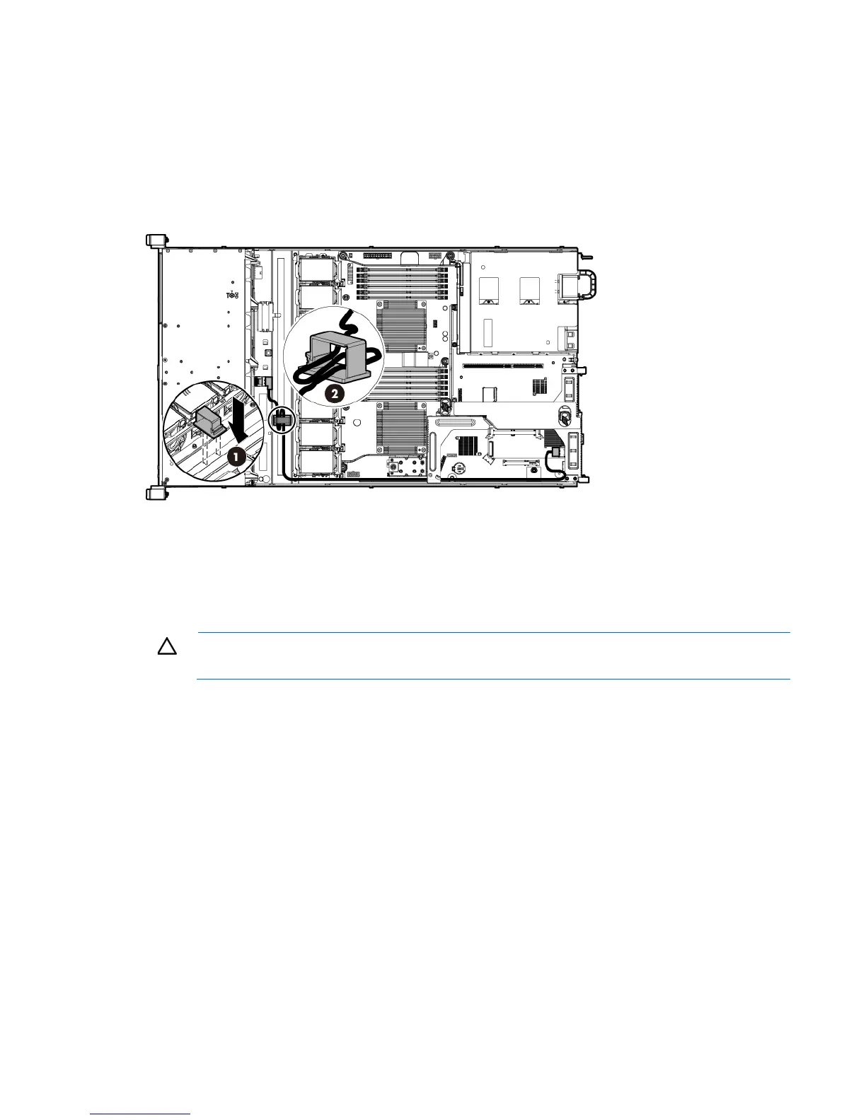
11. In the four-bay LFF drive cage configuration, HP recommends securing the excess length of the Mini-SAS
cable by using the cable clip that came with the kit:
a. Use the two vertical dash marks in front of the fan cage to position the clip correctly, and then attach
the cable clip.
b. Secure the excess length of the Mini-SAS cable in the cable clip.
12. If you intend to use an FBWC module and capacitor pack, install these options now ("Installing the
FBWC module and capacitor pack" on page 39).
13. Install the access panel (on page 20).
14. Install the server into the rack ("Installing the server into the rack" on page 27).
15. Power up the server (on page 17).
CAUTION: To prevent improper cooling and thermal damage, do not operate the server unless
all bays are populated with either a component or a blank.
16. Install the drives ("Installing a hot-plug drive" on page 32).
Mini-SAS Y-cable option
The Mini-SAS Y-cable in this option kit supports HP Smart Array controller board options in the eight-bay SFF
drive configuration.
To connect the cable option:
1. Power down the server (on page 17).
2. Remove all power:
a. Disconnect each power cord from the power source.
b. Disconnect each power cord from the server.
3. Do one of the following:
o Extend the server from the rack (on page 17).
o Remove the server from the rack (on page 18).
 Loading...