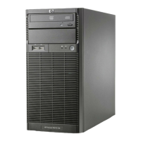
7. Unfasten the thumb screws on both sides to release the system tray.
8. Pull out the system tray.
9. Pull the system tray out until it stops on its own, and there also an
arrow sticker shows, which on the side of the system tray.
10. Disconnect the power cable on the system board.
11. Disconnect the USB cable, Fan cable, Mini SAS cable and LED
cable on the system board.
IMPORTANT: Need completely remove the system tray from the
chassis before attempting to remove or replace any component
on the system board.
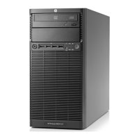
For re-installing the system tray, refer to following procedures:
1. Connect the Mini SAS cable, LED cable and two USB cables to
connectors on system board.
2. Connect the power cable and fan cable to connectors on system
board.
3. Completely push the system tray into the server.
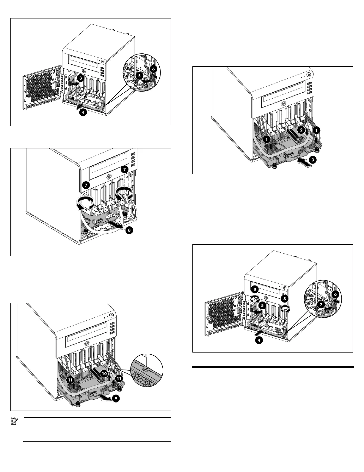
4. Place the power cable under the tray handle in the server. Put the
power cable and fan cable together inside the left cable clamp of
the chassis.
5. Lock the cable clamp to secure the power cable and fan cable.
6. Place the LED cable and two USB cables in the server and also
put them together inside the right cable clamp of the chassis.
7. Lock the cable clamp to secure those cables together.
8. Fasten the two thumb screws on both sides.
Installing a memory module
The system has two DIMM slots that support up to 8 GB maximum
system memory (4 GB in each of the two DIMM slots).
Memory installation guidelines
Observe the following important guidelines when installing memory
modules:
• Use only HP supported unbuffered ECC DDR3 DIMM in 1 GB,
2 GB or 4 GB DIMM capacities.