Contents
PCI-X Expansion Board Slots...........................................................................................................2-29
PCI-X Expansion Slot Cover.............................................................................................................2-30
PCI-X Expansion Boards ..................................................................................................................2-31
PCI-X Slot Release Lever .................................................................................................................2-33
PCI-X Guide Clips ............................................................................................................................2-34
Processor Air Baffle ..........................................................................................................................2-35
Center Wall........................................................................................................................................2-36
IDE CD-ROM Drive .........................................................................................................................2-38
Power Button/LED Assembly ...........................................................................................................2-40
Diskette Drive....................................................................................................................................2-42
Processor Assembly ..........................................................................................................................2-44
Processor Power Module...................................................................................................................2-49
Memory .............................................................................................................................................2-51
Power Supply Backplane...................................................................................................................2-54
System Board ....................................................................................................................................2-56
Processor Cage Assembly .................................................................................................................2-57
Battery ...............................................................................................................................................2-58
Re-entering the Server Serial Number.....................................................................................................2-60
Chapter 3
Diagnostic Tools
Diagnostic Tools Overview .......................................................................................................................3-2
Chapter 4
LED Indicators and Switches
System LEDs .............................................................................................................................................4-1
Front Panel LEDs ................................................................................................................................4-2
Hot-Plug SCSI Hard Drive LEDs........................................................................................................4-3
RJ-45 Connector LEDs .......................................................................................................................4-5
Rear Unit Identification LED Switch..................................................................................................4-6
Hot-Plug Power Supply LEDs.............................................................................................................4-7
Hot-Plug Fan LEDs.............................................................................................................................4-8
System Board LEDs ............................................................................................................................4-9
External Health LED................................................................................................................................4-11
System LEDs and Internal Health LED Status Combinations.................................................................4-12
System Board Switches............................................................................................................................4-14
Non-Maskable Interrupt Switch ........................................................................................................4-15
System Identification Switch.............................................................................................................4-16
System Maintenance Switch..............................................................................................................4-17
System Configuration Settings ................................................................................................................4-18
ROMPaq Disaster Recovery Mode..........................................................................................................4-19
Chapter 5
Specifications
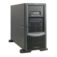
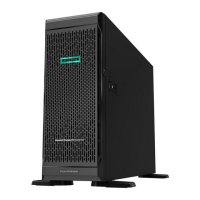
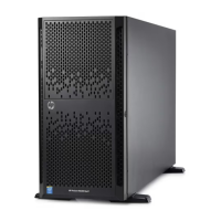
Tower Server..............................................................................................................................................5-2
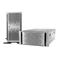
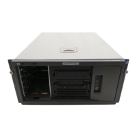
Rack Server................................................................................................................................................5-3
Memory Modules.......................................................................................................................................5-4
1.44-MB Diskette Drive.............................................................................................................................5-5
CD-ROM Drive .........................................................................................................................................5-6
Wide Ultra3 Hot-Plug SCSI Hard Drive....................................................................................................5-8
iv HP ProLiant ML370 Generation 3 Server Maintenance and Service Guide