3 Operating HP 16Gb FC Switches
This chapter discusses switch power, LEDs, maintenance, and management.
Powering the switch on and off
• Power switches are located on the nonport side of the switch.
• If the switch is mounted in a rack, you must remove the plenum to access the power switches.
• Power is supplied to the switch as soon as the first power supply is connected and powered
on.
• To power the switch off, power off the power supplies present by setting the AC power switch
to O. All devices are returned to their initial state the next time the switch is powered on.
LEDs
The switch LEDs indicate system activity and status. There are three LED states: no light, a steady
light, and a flashing light. Flashing lights can be slow, fast, or flickering. The lights are green or
amber.
The LEDs can flash green or amber during boot, POST, or other diagnostic tests. This is normal; it
does not indicate a problem unless the LEDs do not indicate a healthy state after all boot processes
and diagnostic tests are complete.
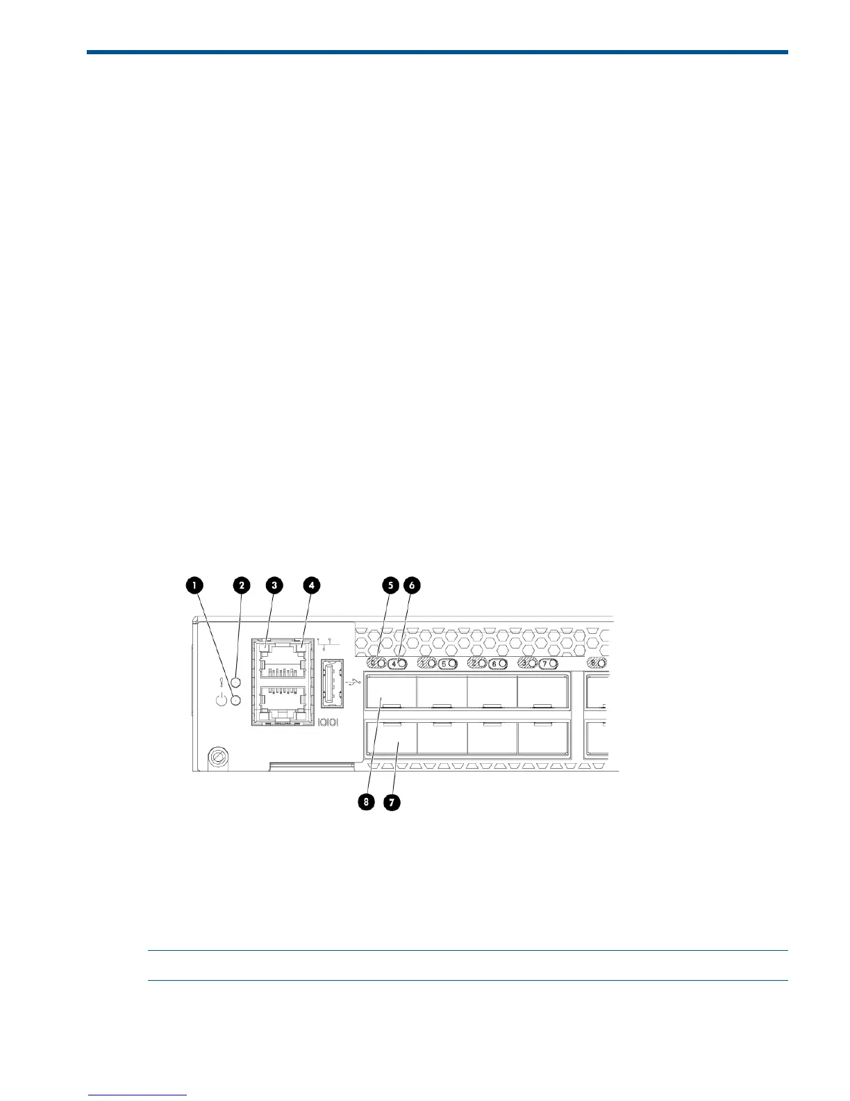
Figure 16 (page 35) shows the port side of the switch. The port status LEDs for the FC ports are
arranged left to right and correspond to the upper and lower ports in each pair. See Figure 1 (page
9).
Figure 16 Port side of the switch
2. System status LED1. System power LED
4. Ethernet port speed LED3. Ethernet port activity LED
6. FC port status LED (port 4)5. FC port status LED (port 0)
8. FC port 07. FC port 4
NOTE: The two LEDs on the serial console port are nonfunctional.
Table 5 (page 36) describes the LEDs on the port side of the switch.
Powering the switch on and off 35
 Loading...