Switch management
You can use the management functions built into the switch to monitor the fabric topology, port
status, physical status, and other information to help you analyze switch performance and to
accelerate system debugging.
For information about upgrading the Fabric OS version installed on your switch, see the Fabric
OS Administrator’s Guide.
You can manage the switch using any of the management tools listed in Table 7 (page 39). See
the Fabric OS 7.0.x Command Reference Manual for more information on the CLI commands.
Table 7 Switch management tools
In-band supportOut-of-band supportManagement tool
IP over FCEthernet or serial connectionCLI
Up to two admin sessions and four user sessions
simultaneously. See the Fabric OS Administrator’s Guide
and the Fabric OS 7.0.x Command Reference Manual.
IP over FCEthernet or serial connectionWeb Tools
See the Web Tools Administrator’s Guide.
IP over FCEthernet or serial connectionStandard SNMP applications
See the MIB Reference Manual.
Native in-band interface
(over HBA only)
Ethernet or serial connectionManagement Server
See the Fabric OS Administrator’s Guide and the Fabric
OS 7.0.x Command Reference Manual.
IP over FCEthernet or serial connectionNetwork Advisor (option to purchase)
See the Network Advisor documentation set.
FRU removal and replacement
The power supply and fan assembly is the only FRU in the switch. No special tools are required
to remove and replace this FRU. The switch will continue to operate during the FRU replacement
if you follow the procedures in this chapter. Replacing a power supply and fan assembly takes
less than two minutes.
CAUTION: Disassembling any part of the power supply voids the part warranty and regulatory
certifications. There are no user-serviceable parts inside the power supply and fan assembly. The
cooling system relies on pressurized air, so do not leave either of the power supply and fan assembly
slots empty longer than two minutes when the switch is operating. If a power supply and fan
assembly fails, leave the power supply and fan assembly in the switch until it can be replaced.
The power supply and fan assembly must be operational to ensure redundancy.
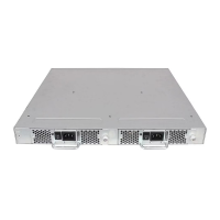
Replacing a power supply and fan assembly
The fans are fixed inside the combined power supply and fan FRU to provide the airflow needed
to cool the switch. Each FRU contains two fans. The system software measures and sets fan speed
through the tachometer interface.
The SN3000B switch comes with one power supply and fan assembly. Fabric OS identifies the
assemblies from right to left on the nonport side. Even though they are contained within a single
unit, the power supply and fan components are identified separately. In the chassisShow command
they are identified as Power Supply Unit:1 and Fan Unit:1.
The SN6000B switch has two power supply and fan assemblies. The two power supply and fan
assemblies are hot-swappable if replaced one at a time. They are identical and fit into either slot.
Switch management 39
 Loading...