Replacing a power supply and fan assembly
To replace the power supply and fan assembly:
1. Ensure that the replacement FRU AC power switch is in the off (O) position.
CAUTION: Damage to the switch can result if the AC power switch is in the on (|) position
when the switch is installed in the chassis.
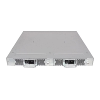
2. Orient the new power supply and fan assembly with the captive screw on the right, as shown
in Figure 17 (page 34).
CAUTION: Do not force the assembly into the chassis. If it does not slide in easily, ensure
that it is oriented correctly before continuing.
3. Gently push the power supply and fan assembly into the chassis until it is firmly seated.
4. Using the Phillips screwdriver, secure the power supply and fan assembly to the chassis by
tightening the captive screw.
5. Plug the power cord into the power supply and fan assembly and power on the unit by setting
the AC power switch to the on (I) position.
6. Verify that the LED on the new power supply and fan assembly displays a steady green light
while the switch is operating. If the LED is not a steady green, ensure that the power supply
is installed securely and seated properly.
7. If the switch is installed in a rack, replace the plenum.
8. Optional: If you are using the CLI, enter the psshow command at the command-line prompt
to display the status. Power supply and fan assembly status can also be viewed using Web
Tools.
Removing and replacing a power supply and fan assembly 35