Do you have a question about the HP V22v G5 and is the answer not in the manual?
Crucial safety precautions and service information for personnel to minimize injury risks and ensure proper operation.
Covers ERP Lot5, RoHS compliance, general descriptions, firmware updates, and customer return procedures.
Details the monitor's specifications, including screen size, resolution, panel type, and connectivity options.
Visual catalog of major monitor components with corresponding item numbers for identification.
Essential steps and materials needed to prepare the monitor for disassembly and service.
Step-by-step instructions and illustrations for disassembling the rear cover of the monitor.
Instructions for disconnecting power board, ITF-BD, and main shield with bezel during disassembly.
Steps for removing control board, USB board, main shield, and middle frame from the monitor.
Details on removing the power board, locating part numbers, and identifying high-voltage areas for safe repair.
Specifics on capacitor repair for out-of-warranty monitors, including ESD, lead-free solder, polarity, and testing.
Steps for capacitor repair, including disconnecting power, measuring charge, and discharging capacitors before replacement.
Instructions for lifting, placing, and soldering new capacitors, emphasizing polarity matching and solder quality.
Identifies the HDMI connector (J3) on the main board and outlines preparation steps for its repair.
Detailed procedure for repairing the HDMI connector, including desoldering, hot air gun use, and component soldering.
Instructions for cutting, applying, and securing a gasket onto the HDMI shielding to prevent short circuits.
Describes how to perform an HDMI test to confirm image and sound display correctly after repair.
A table listing common monitor problems, their causes, and recommended solutions for troubleshooting.
This document serves as a Maintenance and Service Guide for the HP V22v G5 model monitor, providing comprehensive information for trained service personnel. It outlines procedures for spare parts, removal and replacement of components, diagnostic tests, and problem troubleshooting. The guide emphasizes safety information and precautions, ensuring proper service methods for reliable equipment operation.
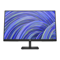
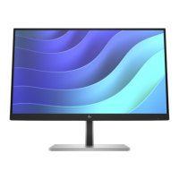
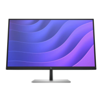
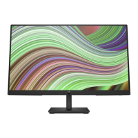
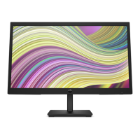
The HP V22v G5 monitor is a display device designed for various computing and gaming applications. It features a screen area with a specific resolution, a Vertical Alignment (VA) panel, and a nonglare panel with an LED backlight, offering a wide viewing angle for comfortable viewing from different positions. The monitor includes tilt capabilities for ergonomic adjustment and a removable stand, allowing for flexible monitor head mounting solutions. For quick attachment and removal, it incorporates an HP Quick Release 2 device.
Connectivity options include a High-Definition Multimedia Interface™ (HDMI) video input and a VGA video input, enabling connection to source devices such as computers or game consoles. The monitor is equipped with a 4-way on-screen display (OSD) controller, which can be reconfigured for quick selection of frequently used operations. It also supports Plug and Play functionality, if supported by the operating system, and features a VESA® mounting bracket for attaching the monitor head to wall-mount devices or swing arms. For security, a security cable slot is provided on the rear, and a cable management feature helps organize cables and cords. The monitor also includes on-screen adjustments in multiple languages for easy setup and optimization, as well as an energy saver feature to meet requirements for reduced power consumption.
The monitor is designed for ease of use with its intuitive front and rear components. On the front, a power button allows users to turn the monitor on or off, and a power LED indicates its operational status. The rear of the monitor houses essential connectors: a security cable slot for an optional security cable, a power connector for the AC adapter, an HDMI port for connecting to high-definition source devices, and a VGA port for connecting to devices using a VGA cable.
The OSD controller provides a user-friendly interface for adjusting various screen settings and optimizing the display. Users can access on-screen adjustments in several languages, making setup and customization accessible globally. The energy saver feature helps reduce power consumption, aligning with environmental and cost-saving considerations. The monitor's design, including the removable stand and VESA mounting bracket, offers flexibility in placement and setup, catering to different user preferences and workspace configurations.
The Maintenance and Service Guide provides detailed instructions for servicing the HP V22v G5 monitor, intended for professional service technicians in a repair center. End users are explicitly advised not to perform these procedures. The guide outlines two levels of service: cosmetic/appearance/alignment service and circuit board or standard parts replacement.
Key maintenance procedures include:
The guide also provides information on ordering spare parts, including power boards, capacitors, and connectors, and directs technicians to HP PartSurfer for complete and current information on supported parts. It also lists EU distributors for internal and external power supplies. The document adheres to RoHS (Restriction of Hazardous Substance) requirements, emphasizing the use of compliant parts and lead-free solder. It also references ERP Lot5 requirements for professional repairers, including technical competence and insurance coverage.
| Display Size | 21.5 inches |
|---|---|
| Panel Type | VA |
| Refresh Rate | 75 Hz |
| Aspect Ratio | 16:9 |
| Brightness | 250 nits |
| VESA Mount | 100 x 100 mm |
| Resolution | 1920 x 1080 |
| Response Time | 5 ms |
| Ports | 1 x VGA; 1 x HDMI 1.4 |
| Viewing Angle | 178° horizontal / 178° vertical |
| Contrast Ratio | 3000:1 |