41
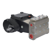
DIAGRAM OF HOW TO MOUNT THE HEAD SCREWS
WARNING: to tighten the head screws, please refer strictly to the torque prescribed (See the table
on page 43 - item 1) and to the tightening order as per the following diagram
Diagram showing the sequence for tightening the head screws.
SERVICING THE HYDRAULIC PART
The head unit requires no maintenance, only a simple check to verify the condition of the valves.
If there are anomalous pressure oscillations, inspect the valves and change them if they are damaged
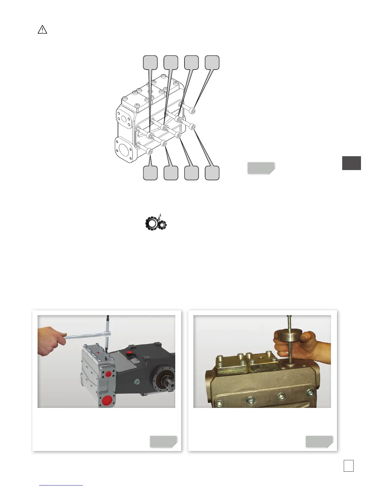
Inspecting the hydraulic parts (refer to the exploded drawing in Fig. 22)
Unscrew the 12 screws (item 5) of the valve
caps (items 6 and 7).
01 Screw down the extractor on the valve
guide body
02
6 4 2 7
8 1 3 5
 Loading...