6
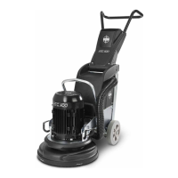
Exploded diagram, HTC 650 chassis
1
2
3
4
6
5
7
8
9
10
11
12
13
14
15
16
17
18
19
20
21
23
24
25
26
27
28
29
30
31
32
33
34
35
36
37
38
39
40
15
41
42
43
44
45
46
47
22
48
49
22
50
12
Parts list, HTC 650 chassis
No. Description Art. No. Qty
1 Water tank HTC 650/800 (2005) 111342 1
2 Hose large reinforced PVC 111104 1
3 Water valve to grinder 110007 1
4 Chassis HTC 800 HDX 111382 1
5 Handle complete HTC 800 CE 111374 1
6 Power Unit 11 kW CE 111400 1
7 Spacer screw HTC 650 310255 2
8 Screw MC6S M6X16 8.8 galvanised 310082 2
9 Screw MC6S M835 8.8 galvanised 310189 4
10 Wear protection upper HTC 650 111404 2
11 Screw thermoplastic PT WN 1452 TX 310148 6
12 Washer BRB M6 galvanised 310012 2
13
Washer BRB M8 galvanised 310077 4