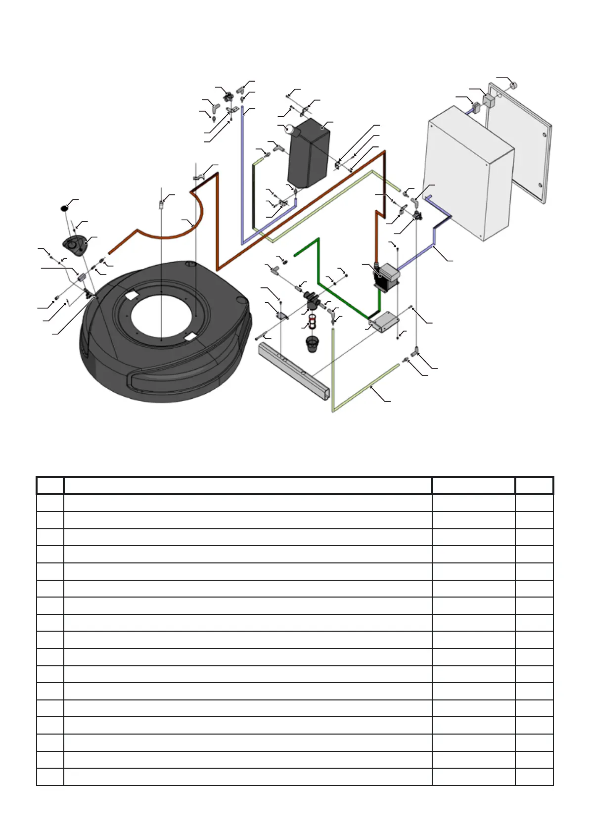
28
No. Description Art. No. Qty
1 Screw MC6S M5x12 310140 14
2 Fixing plate ball valve, Left HTC 800 10977 2
3 Hose connection 2601-12-1/4 110205 7
4 Elbow piece MF 2020-1/4 110146 7
5 Water valve to grinder 110007 2
6 Screw 310148 3
7 Attachment 2 water tank 111446 1
8 Water tank 950 111507 1
9 Pipe cover for suction casing 10585 1
10 Attachment 3 water tank 111447 1
11 Attachment water tank 111443 1
12 Screw MC6S M6X16 8.8 galvanised 310082 6
13
Pump EH-C15VC-PR2-IPVC 111394 1
14
May be due to poorly connected supply cables. 111586 1
15 CONTACT BLOCK ZBE-101 (NO) 110492 2
16 Mounting base, metal 10983 1
17 Operating Device, black knob, 2 positions 111574 1
Parts list HTC 950 Mist Cooler System
1
1
2
3
3
3
4
5
29
28
4
4
3
3
3
6
1
7
8
1
6
1
6
9
4
2
5
10
12
11
4
14
15
16
12
13
17
18
3
4
19
20
23
21
4
22
23
24
25
26
27
25
32
24
31
23
35
33
34
36
37
30
38
31
39
Exploded diagram, HTC 950 Mist Cooler System