LP-605 Rev. 000 Rel. 009 Date 8.16.18
29
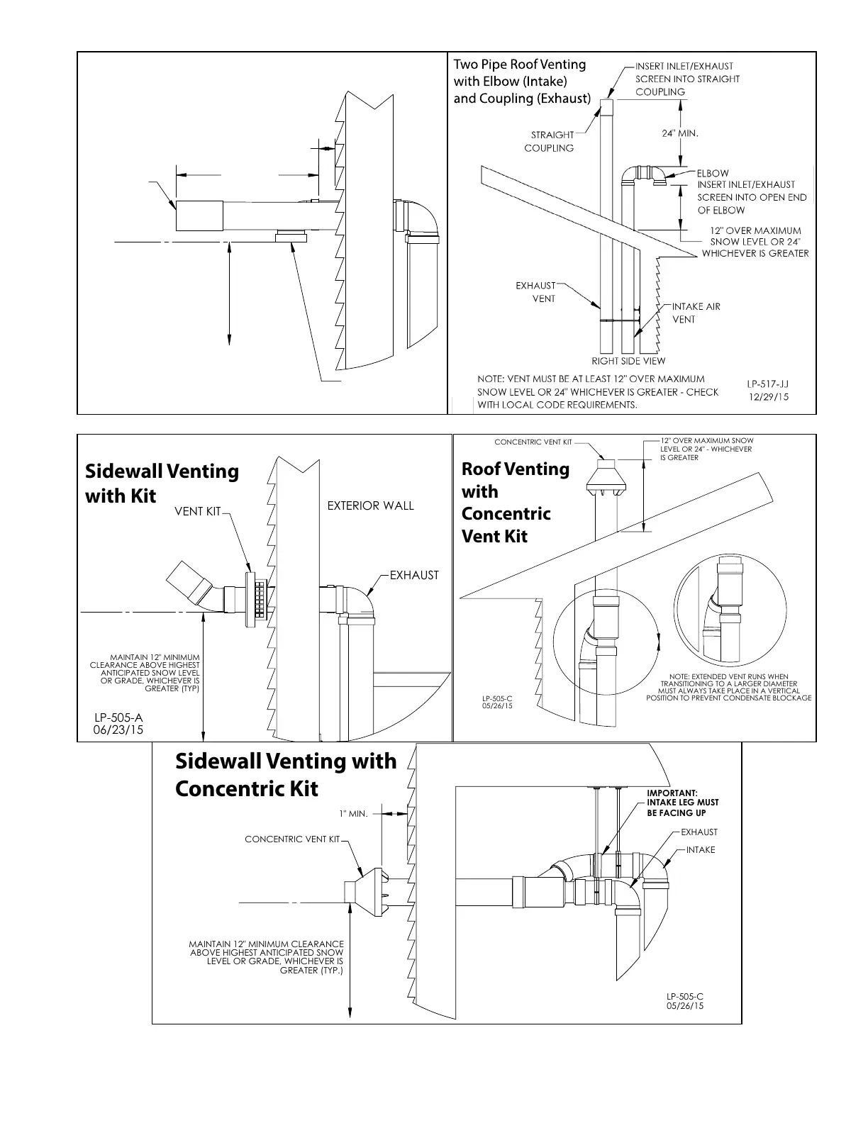
Figure 20 - Direct Vent, Roof and Sidewall Vent Terminations
NOTE: These drawings are meant to demonstrate system venting only. The installer is responsible for all equipment and detailing required
by local codes.
12" MIN.
MAINTAIN 12" MINIMUM
CLEARANCE ABOVE HIGHEST
ANTICIPATED SNOW LEVEL
OR GRADE, WHICHEVER IS
GREATER (TYP)
EXTERIOR WALL
EXHAUST
INTAKE
1" MIN.
06/23/15
LP-505-A
Two Pipe Sidewall Venting
with Elbow (Intake)
and Coupling (Exhaust)
INSERT EXHAUST
SCREEN
INSERT INLET SCREEN
Two Pipe Roof Venting
with Elbow (Intake)
and Coupling (Exhaust)
GREATER (TYP)
MAINTAIN 12" MINIMUM
CLEARANCE ABOVE HIGHEST
OR GRADE, WHICHEVER IS
VENT KIT
EXHAUST
ANTICIPATED SNOW LEVEL
EXTERIOR WALL
06/23/15
LP-505-A
Sidewall Venting
with Kit
05/26/15
LP-505-C
INTAKE
IMPORTANT:
EXHAUST
INTAKE LEG MUST
BE FACING UP
CONCENTRIC VENT KIT
MAINTAIN 12" MINIMUM CLEARANCE
ABOVE HIGHEST ANTICIPATED SNOW
LEVEL OR GRADE, WHICHEVER IS
GREATER (TYP.)
1" MIN.
Sidewall Venting with
Concentric Kit
12" OVER MAXIMUM SNOW
LEVEL OR 24" - WHICHEVER
IS GREATER
05/26/15
LP-505-C
CONCENTRIC VENT KIT
POSITION TO PREVENT CONDENSATE BLOCKAGE
NOTE: EXTENDED VENT RUNS WHEN
TRANSITIONING TO A LARGER DIAMETER
MUST ALWAYS TAKE PLACE IN A VERTICAL
Roof Venting
with
Concentric
Vent Kit
Figure 21 - Direct Vent, Vent Terminations with Optional Kits (NOT INCLUDED WITH THE APPLIANCE)

 Loading...