lp-608 Rev. 000 Rel. 001 Date 3.15.18
10
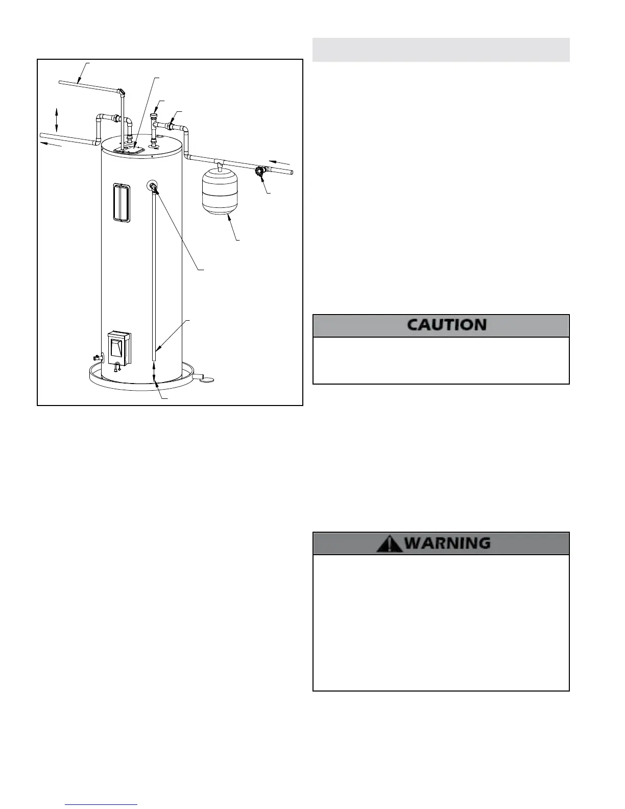
H. Applications
11/15/16
6" MINIMUM
INLET
FIXTURES
OUTLET TO
COLD WATER
HEAT TRAP
HOT WATER
LP-608-D
6" AIR GAP
TO ELECTRICAL
DISTRIBUTION PANEL
VACUUM BREAKER
RELIEF VALVE DISCHARGE
LINE TO SUITABLE OPEN DRAIN
SHUT-OFF
VALVE
TEMPERATURE/PRESSURE
RELIEF VALVE
UNION
THERMAL EXPANSION
TANK
ELECTRICAL JUNCTION
BOX
Figure 4 - Piping Detail - NOTE: Drawing is meant to demonstrate system
piping concept. Heat traps are optional.
PIPING NOTES:
The following notes are applicable to all of the piping applications
demonstrated on this page.
1. Minimum pipe size should match connection size. Upsize pipe
accordingly if greater ow is required.
2. A thermal expansion tank suitable for potable water must be
sized and installed within this piping system between the backow
preventer and the cold water inlet.
3. All circulators should have an integral ow check.
4. Drains and check valve between unit and storage tank will assist in
purging air from system.
5. These drawings are meant to demonstrate system piping only. The
qualied installer / service technician is responsible for all equipment
and detailing required by local codes. In Massachusetts, you MUST
install a vacuum relief valve per 248 CMR. Some installations (attic
installations, for example) in other locales may also require a vacuum
relief valve. Consult the AHJ and local codes to prevent vacuum related
damage to the water heater. Vacuum related damages ARE NOT
covered by product warranty.
6. Mixing valve application is optional, but recommended to help
prevent scalding. See Part 3 for more information.
Part 4 - Wiring
Tank must be full of water before the power is turned on. Heating
elements will be damaged if energized for even a short time
while tank is dry. Failures due to “dry-ring” ARE NOT covered by
warranty.
This unit is factory wired to a junction box on top of the water heater
for eld wiring connection. These heaters are equipped and wired
for the maximum possible input allowable (see Table 3 for listing of
inputs and amperage requirements). The voltage requirement and
dedicated wattage load for the heater is specied on the rating label
of the water heater. Consult your electrician or a qualied technician
to determine if your electrical service is adequate for the additional
load of the heater.
Refer to the wiring diagrams for eld connections. All wiring must
conform to all local, state, and the National Electric Code and
regulations and should be done by a qualied licensed electrician.
The water heater must be electrically grounded as part of the
electrical connections.
NOTE: 80 gallon and larger water heaters are locked per Federal
Regulations. The water heater is intended to be used for thermal
energy storage by the utility. See Figure 8 for a detail of the lock.
Contact the utility to unlock the box, enable the lower element, and
adjust the lower thermostat.
This water heater is equipped with a disabled lower heating element.
The utility must manually enable the lower element for it to operate.
A. Communication
C. Field Wiring Details
1. Remove the lock from the box.
2. Use a Phillips Head screwdriver to remove the screw from the
bottom of the water heater lock box.
3. Open the water heater lock box.
4. Pull the handle to remove the activation switch marked “OFF”
from the socket. See Figure 5 for details.
5. Flip the activation switch so that it reads “ON” and push it back
into the socket. The lower element is now ready to operate.
6. Close the box. Use a Phillips Head screwdriver and reinstall the
screw removed in Step 2.
7. Lock the box.
B. Enabling the Lower Element
HAZARDOUS VOLTAGE: Risk of electric shock. Can cause injury or
death. This water heater must be electrically grounded as part of
the electrical connection. Grounding must include at least one of
the following:
• A metallic conduit or metallic sheathed cable assembly
suitable for this application with approved ttings
• A non metallic sheathed cable with a grounding conductor
suitable for this application.
Electrical connections and materials must meet the requirements
of all local, state, and the National Electric Code and regulations.
Failure to follow these instructions could result in property
damage, severe personal injury, or death.