LP-428 Rev. 6.6.16
14
C. Backow Preventer
Use a backow preventer specically designed for boiler
installations. This valve should be installed on the cold water
ll supply line per local codes.
D. Expansion Tank
Expansion Tank and Make-Up Water
1. Ensure that the expansion tank is sized to correctly handle
boiler and system water volume and temperature.
B. Relief Valve
To avoid water damage or scalding due to relief valve operation:
• Discharge line must be connected to relief valve outlet
and run to a safe place of disposal. Terminate the
discharge line in a manner that will prevent possibility of
severe burns or property damage should the relief valve
discharge.
• Discharge line must be as short as possible and the same
size as the valve discharge connection throughout its
entire length.
• Discharge line must pitch downward from the valve
and terminate at least 6” above the oor drain, making
discharge clearly visible.
• The discharge line shall terminate plain, not threaded,
with a material serviceable for temperatures of 375
o
F or
greater.
• Do not pipe discharge to any location where freezing
could occur.
• No valve may be installed between the relief valve and
boiler or in the discharge line. Do not plug or place any
obstruction in the discharge line.
• Test the operation of the relief valve after lling and
pressurizing the system by lifting the lever. Make sure
the valve discharges freely. If the valve fails to operate
correctly, immediately replace with a new properly rated
relief valve.
• Test T&P valve at least once annually to ensure the
waterway is clear. If valve does not operate, turn the
boiler “o” and call a plumber immediately.
• Take care whenever operating relief valve to avoid
scalding injury or property damage.
FAILURE TO COMPLY WITH THE ABOVE GUIDELINES
COULD RESULT IN FAILURE OF RELIEF VALVE OPERATION,
RESULTING IN POSSIBILITY OF SUBSTANTIAL PROPERTY
DAMAGE, SEVERE PERSONAL INJURY, OR DEATH.
Connect discharge piping to a safe disposal location following
the guidelines below.
RE-INSPECTION OF T&P RELIEF VALVES: T&P valves should
be inspected AT LEAST ONCE EVERY THREE YEARS, and
replaced if necessary, by a licensed plumbing contractor or
qualied service technician to ensure that the product has not
been aected by corrosive water conditions and to ensure that
the valve and discharge line have not been altered or tampered
with illegally. Certain naturally occuring conditions may corrode
the valve and its components over time, rendering the valve
inoperative. Such conditions can only be detected if the valve
and its components are physically removed and inspected.
Do not attempt to conduct an inspection on your own.
Contact your plumbing contractor for a re-inspection to assure
continued safety.
Do not thread a cap or plug into the relief valve or relief valve
line under any circumstances! Explosion and property damage,
serious injury, or death may result.
FAILURE TO RE-INSPECT THE T&P VALVE AS DIRECTED
COULD RESULT IN UNSAFE TEMPERATURE AND/OR
PRESSURE BUILD-UP WHICH CAN RESULT IN PROPERTY
DAMAGE, SERIOUS PERSONAL INJURY, OR DEATH.
Undersized expansion tanks cause system water to be lost
from the relief valve, causing make-up water to be added.
Eventual boiler failure can result due to excessive make-
up water addition. SUCH FAILURE IS NOT COVERED BY
WARRANTY.
Expansion tanks must be sized according to total system
volume. This includes all length of pipe, all xtures, boilers,
etc. Failure to properly size for system expansion could result
in wasted time, money, possible property damage, serious
injury, or death.
DO NOT install automatic air vents on closed type expansion
tank systems. Air must remain in the system and return to the
tank to provide an air cushion. An automatic air vent would
cause air to leave the system, resulting in improper operation
of the expansion tank.
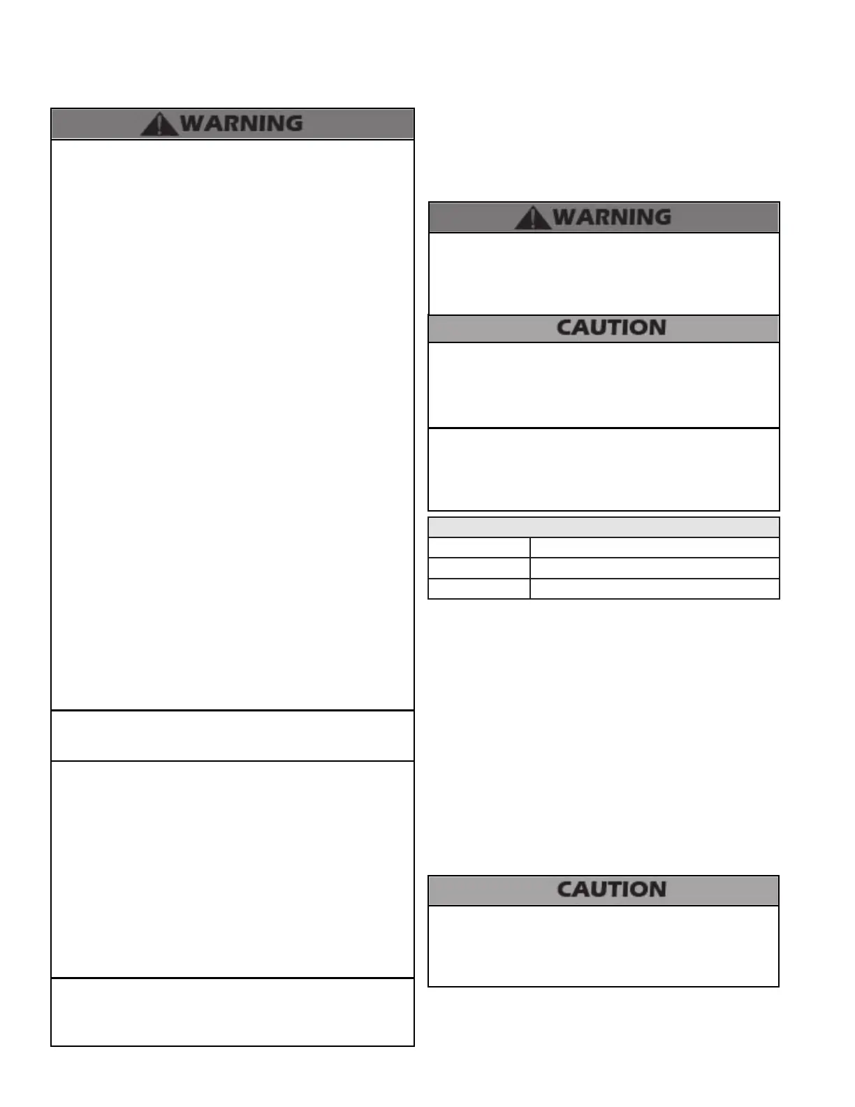
Expansion Tank Sizing
Model Heat Exchanger Volume (Gallons)
MODCON1000 8.4
MODCON1700 11.6
Table 2 - ModCon Heat Exchanger Volume
E. Circulators
Sizing Space Heat System Piping
1. In all diagrams, the space heating system is isolated from
the boiler loop by the primary / secondary connection.
DO NOT use the boiler circulator in any location other than
the ones shown in this manual. The boiler circulator location
is selected to ensure adequate ow through the boiler.
Failure to comply with this caution could result in unreliable
performance and nuisance shutdowns from insucient ow.
2. The expansion tank must be located as shown in
Applications, this manual, or following recognized design
methods. See expansion tank manufacturer’s instructions for
details. Always install an expansion tank designed for potable
water systems.
3. Connect the expansion tank to the air separator only if the
separator is on the suction side of the circulator. Always install
the system ll connection at the same point as the expansion
tank connection to the system.
4. Most chilled water systems are piped using a closed type
expansion tank.
Diaphragm (or Bladder) Expansion Tank
Always install an automatic air vent on top of the air separator
to remove residual air from the system.