LP-428 Rev. 6.6.16
32
D. Line Voltage Wiring
1. Connect the incoming power wiring to the line voltage
terminal strip in the electrical junction box at terminals 120V,
Neutral, Ground of the bottom boiler (shown in Figure 20).
2. A line voltage fused disconnect switch may be required,
externally mounted and connected according to local codes that
may apply.
3. Connect the central heating pump motor starter coil to the
terminals marked BOILER HOT, BOILER NEUT, and BOILER
GRD in the bottom boiler.
4. If using DHW, connect the domestic hot water pump to
the terminals marked DHW HOT, DHW NEUT, DHW GND on
the bottom boiler. The connections shown are suitable for
a maximum continuous pump draw of 3 amps at 120 volts.
If a pump requires more current or voltage than the 120 volts
supplied, an external motor starter or contactor will be required.
E. Alarm Connections (Top Boiler Connection)
The control includes a dry contact alarm output. This is an SPDT
circuit, rated at 5 amps at 120 volts. This contact can be used to
activate an alarm light or bell or notify a building management
system if the boiler goes into a lockout condition. The circuit
between the ALARM COM and NC terminals is closed during
normal operation and the circuit between ALARM COM and
NO is open during normal operation. The connections depicted
in Figure 20 show two 120 volt lights connected to the alarm
terminals. One light will be on when the boiler is in normal mode
and the other light will be on when the boiler is in lockout mode.
F. Low Voltage Connections for Standard Boiler
1. All low voltage cables should enter the electrical junction box
through the provided knock out holes as shown in Figure 19.
2. Connect all low voltage eld devices to the low voltage
terminal strip located in the electrical junction box.
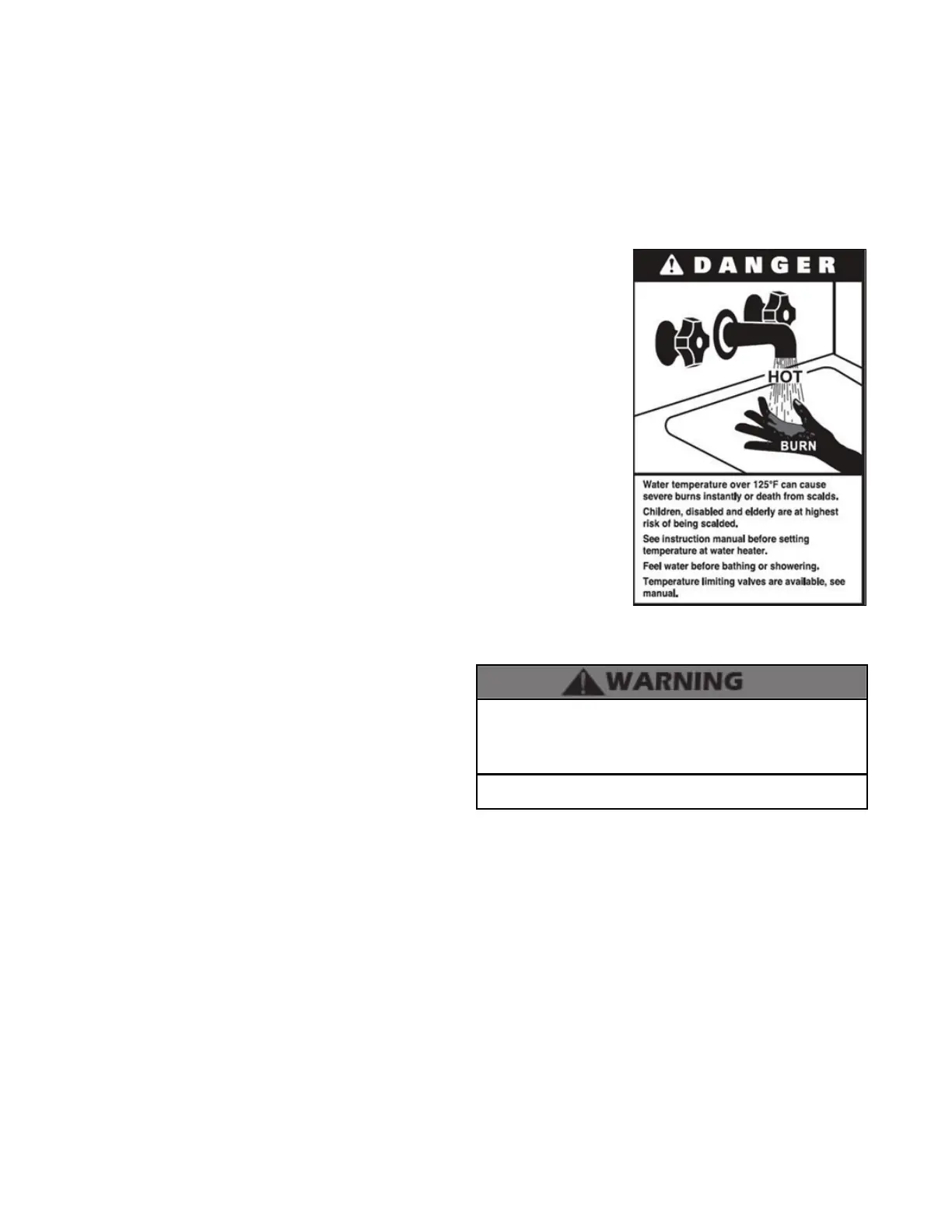
Failure to use the correct sensor may result in tank
temperature being either above or below set point, and
could result in decreased performance, substantial property
damage, or heightened risk of injury or death due to scalds.
H. Outdoor Sensor
1. There is no connection required if an outdoor sensor is not
used in this installation.
2. If using an outdoor sensor, connect wires for sensor to the
terminals marked OUTDOOR SEN (shown in Figure 20) in the
electrical junction box of the bottom boiler. Caution should be
used to ensure neither of these terminals becomes connected
to ground.
3. Use a minimum 22 AWG wire for runs of 100 feet or less and
minimum 18 AWG wire for runs of up to 150 feet.
Caution should be used to ensure neither of these terminals
becomes connected to ground.
NOTE: If sensor wires are located in an area with sources of
potential electromagnetic interference (EMI), the sensor
wires should be shielded, or the wires routed in a grounded
metal conduit. If using shielded cable, the shielding should be
connected to the common ground of the boiler.
G. Thermostat
1. Connect the room thermostat to the terminals marked
THERMOSTAT in the electrical junction box (shown in Figure
20). Alternately, any dry contact closure across these terminals
will cause the boiler to run. Caution should be taken to ensure
neither of the terminals becomes connected to ground.
2. Mount the thermostat on an inside wall as centrally as possible
to the area being heated, but away from drafts or heat producing
devices such as television sets that could inuence the ability of
the thermostat to measure room temperature.
3. If the thermostat is equipped with an anticipator and it is
connected directly to the Mod Con boiler, the anticipator should
be set at .1 amps. If the thermostat is connected to other devices,
the anticipator should be set to match the power requirements
of the device it is connected to. See the instruction manual of
the connected devices for further information.
4. Mount the outdoor sensor on an exterior surface of the
building, preferably on the north side in an area that will not
be aected by direct sunlight and will be exposed to varying
weather conditions.
I. Indirect Sensor (Top Boiler Connection)
1. There is no connection required if an indirect water heater is
not used in this installation.
2. The boiler will operate an indirect red water heater with
either a thermostat type aquastat installed in the indirect
tank, or an HTP 7250P-325 tank sensor. When a tank sensor
is used, the control will
automatically detect its
presence and a demand
for heat from the
indirect water heater
will be generated when
the tank temperature
falls below the user
selected set point by
more than the user
selected oset. The
demand will continue
until the sensor
measures that the
indirect water heater
temperature is above
the set point.
3. Connect the indirect
tank sensor (7250P-325)
to the terminals marked
DHW SENSOR (shown in Figure 20) in the electrical junction
box of the top boiler.
J. Optional 0-10 Volt Building Control Signal
1. A signal from a building management system may be
connected to the boiler to enable remote control. This signal
should be a 0-10 volt positive-going DC signal. When this input
is enabled using the installer menu, a building control system
can be used to control the set point temperature of the
boiler. The control interprets the 0-10 volt signal as follows;
when the signal is between 0 and 1.5 volts, the boiler will be
in standby mode, not ring. When the signal rises above 1.5
volts, the boiler will ignite. As the signal continues to rise
towards its maximum of 10 volts, the boiler will increase in
set point temperature. See Part 10 for details on the setting of
parameters 16 and 17.
2. Connect a building management system or other auxiliary