LP-428 Rev. 6.6.16
49
Press v once.
CASCADE PWR 100%
PRESENT 01234567
This screen displays overall cascade
power output. The range of this
value is the number of boilers
communicating with the Master x
100. For example, if 8 boilers are
connected and ring, the maximum
cascade power is 800%. The second
line shows which boiler addresses
are communicating with the Master.
Press v once.
CASCADE SYST 118
o
F
CASCADE SET 190
o
F
This screen displays current system
temperature sensor reading on the
top line and the cascade system
temperature setting on the bottom.
Press v once.
BOILER 0 100%
BOILER 1 56%
This screen displays the current
cascade power demand output
on a per connected boiler basis
for boilers addressed as 0 and 1.
In the example, boiler 0 is being
commanded to re at 100% and
boiler 1 at 56%. If this were a 2 boiler
system, the ‘CASCADE PWR’ screen
above would read 156%.
Press v once.
BOILER 2 0%
BOILER 3 0%
This screen displays the current
cascade power demand output on a
per connected boiler basis for boilers
addressed as 2 and 3.
Press v once.
BOILER 4 0%
BOILER 5 0%
This screen displays the current
cascade power demand output on a
per connected boiler basis for boilers
addressed as 4 and 5.
Press v once.
BOILER 6 0%
BOILER 7 0%
This screen displays the current
cascade power demand output on a
per connected boiler basis for boilers
addressed as 6 and 7.
Table 23 - Cascade Menu
C. Boiler Test Mode
This function is intended to simplify gas adjustment. The
following tables include recommended combustion settings
by fuel type and boiler fan speeds. Automatic modulation does
not take place while the controller is in Test Mode. However,
the boilers will modulate down if the program set point is
reached while running in Test Mode. It is recommended to
enter Test Mode with the largest load possible to create such a
heat demand that Test Mode will not be interrupted. To enter
Test Mode press ^ and ENTER simultaneously.
NOTE: The boiler will automatically exit Test Mode after 20
minutes of operation.
To leave Test Mode press ^ and v simultaneously.
SERVICE RUN 3400 RPM
PUMP ON 4:49P
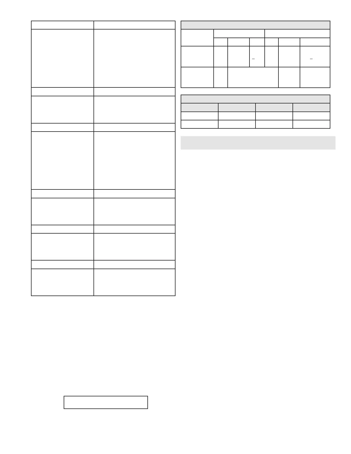
Combustion Settings on All Models
Fan Speed
Natural Gas (NG) Propane (LP)
Low Ignition High Low Ignition High
Carbon
Monoxide
(CO) PPM
5-50 35-100
<150 5-50 35-100 <150
Carbon
Dioxide
(CO
2
) %
8-10 8 1/2-10 1/2 9-10 1/2 9 1/2-11
Table 21 - Combustion Settings - All Models
Fan Speeds
Model Ignition Min Max
1000 3000 1950 7200
1700 3000 2200 6800
Table 22 - Fan Speeds
Part 11 - Troubleshooting
A. Boiler Error and Fault Codes
If any of the sensors detect an abnormal condition, or an internal
component fails during the operation of the boiler, the display may
show an error message and error code. This message and code may
be the result of a temporary condition, in which case the display
will revert to its normal readout when the condition is corrected, or
it may be a condition that the controller has evaluated as not safe
to restart the boiler. In this case, the boiler control will be locked
out, the red FAULT light will be lit, and the message “LOCKOUT”
will be displayed on the readout in the lower line.
The boiler will not start until a qualied technician has repaired
the boiler and pressed the RESET button for more than 1 second.
If there is an error message displayed on the readout, and the
message “LOCKOUT” is not displayed and the FAULT light is not
lit, then the message is the result of a temporary condition and will
disappear when the problem corrects itself.
IMPORTANT NOTE: If you see error messages on your display
readout, call a technician immediately, since the message may
indicate a more serious problem will occur soon.
B. Boiler Error
The controller will display an error code and message when
an error condition occurs. These error codes, descriptions, and
recommended corrective actions are described in Section D.
C. Boiler Fault
1. The controller will illuminate the red “FAULT” indication light
and display a fault code and message when a fault condition
occurs. The alarm output will also activate. Most fault conditions
cause the CH pump to run in an attempt to cool the boiler.
2. Note the displayed fault code and refer to Section D for an
explanation of the message along with several suggestions for
corrective actions.
3. Press RESET to clear the fault and resume operation. Be sure
to observe the operation of the unit for a period of time to assure
correct operation and no reoccurrence of fault message.

 Loading...


