LP-428 Rev. 6.6.16
37
Never use an open ame (match or lighter) to check for gas
leaks. Use a soapy solution to test connection. Failure to use
a soapy solution test or check gas connection for leaks can
result in substantial property damage, severe personal injury,
or death.
Use two wrenches when tightening gas piping at the boiler:
One to prevent the boiler gas line from turning. Failure to
prevent the boiler gas connection from turning could result
in damage to the gas line components, substantial property
damage, severe personal injury, or death.
CSA or UL listed exible gas connections can be used when
installing the boiler. Flexible gas connections have dierent
capacities and must be sized correctly for the connected
boiler ring rates. Consult with the ex line supplier to assure
the line size is adequate for the job. Follow local codes for
proper installation and service requirements.
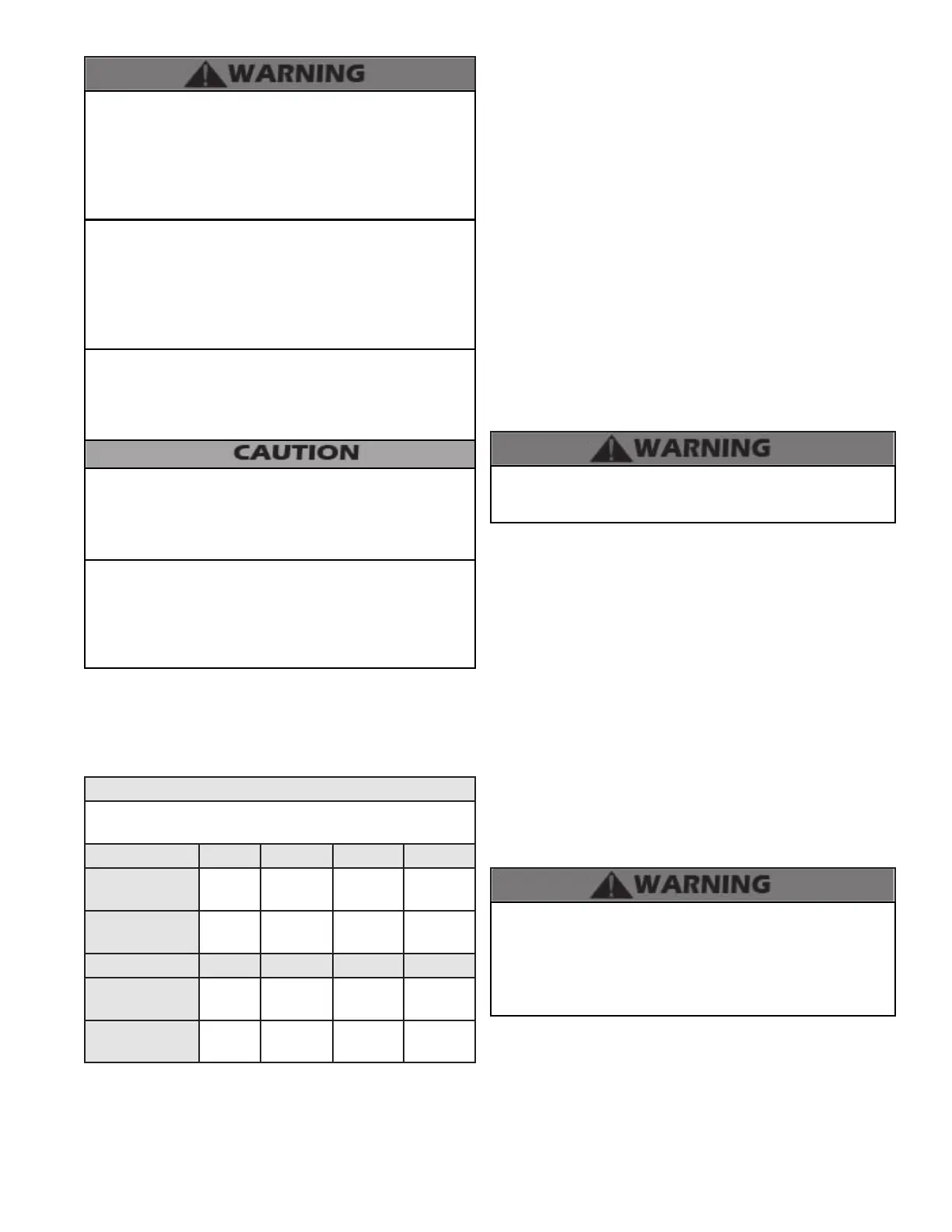
B. Gas Table
Refer to Table 11 to size the supply piping to minimize pressure
drop between the meter or regulator and unit. Maximum
capacity of pipe in cubic feet of gas per hour for gas pressures
of .5 w.c. or less and a pressure drop of .3 inch w.c.
Natural Gas Supply Piping Capacity Chart
(0.6 Specic gravity gas; 0.5” WC pressure drop)
*Schedule 40 iron pipe size in nominal inches
Model 1 Unit 2 Units 3 Units 4 Units
MODCON1000
@ 100’ of Pipe
2” 3” 3” 4”
MODCON1000
@ 250’ of Pipe
2 1/2” 3” 4” 4”
Model 1 Unit 2 Units 3 Units 4 Units
MODCON1700
@ 100’ of Pipe
2 1/2” 4” 4” 5”
MODCON1700
@ 250’ of Pipe
3” 4” 5” 5”
Table 11 - Gas Supply Piping Size Chart for Boilers
Support gas supply piping with hangers, not by the boiler
or its accessories. The boiler gas valve and blower will not
support the weight of the piping. Make sure the gas piping
is protected from physical damage and freezing, where
required. Failure to follow these instructions could result in
gas leakage, and result in re, explosion, property damage,
severe personal injury, or death.
Do not use Teon tape on gas line pipe thread. Use a pipe
compound rated for use with natural and propane gases.
Apply sparingly on male pipe ends, leaving the two end
threads bare and ow unobstructed. Failure to follow these
instructions could result in gas leakage or blockage, and
result in re, explosion, property damage, severe personal
injury, or death.
C. Check Inlet Gas Pressure
The gas valve is equipped with an inlet gas pressure tap that
can be used to measure the gas pressure to the unit. To check
gas pressure, perform the steps listed below:
1. IMPORTANT! Before you connect to the inlet pressure,
shut o the gas and electrical power to unit.
2. Loosen the pressure tap with a small screwdriver. Refer to
Figures 25 and 26 for location.
3. Each unit is equipped with a needle valve that will accept a
5/16 ID hose to connect to a digital manometer or liquid gauge
to measure incoming pressure from 0-35” w.c.
4. Turn on the gas and power up the unit.
5. Put the unit into manual test mode (details on test mode in
Part 10). In test mode, monitor pressure to assure it does not
drop below 1 inch from its idle reading. If gas pressure is out
of range or pressure drop is excessive, contact the gas utility,
gas supplier, qualied installer, or service agency to determine
correct action that is needed to provide proper gas pressure to
the unit. If Gas Pressure is within normal range proceed to Step
6.
6. Exit test mode, then turn power o and shut o gas supply at
the manual gas valve before disconnecting the hose from the
gas monitoring device. Tighten screw on the pressure tap and
turn gas on. Check for leaks with soapy solution. Bubbles will
appear on the pipe to indicate a leak is present.
Ensure the pressure tap screw is properly tightened to prevent
gas leaks. Failure to do so could cause substantial property
damage, severe personal injury, or death.
The gas piping must be sized for the proper ow and length of
pipe to avoid pressure drop. The gas meter and regulator must be
properly sized for the total gas load. If you experience a pressure
drop greater than 1” w.c. (.87 kPa), the meter, regulator or gas
line may be undersized or in need of service. You can attach a
manometer to the incoming gas drip leg after removing the cap.
The gas pressure must remain between 3.5” (.87 kPa) and 14”
(3.5 kPa) during stand-by (static) mode and while in operating
(dynamic) mode.
If an in-line regulator is used, it must be a minimum of 10 feet
from the boiler. It is very important that the gas line is properly
purged by the gas supplier or utility. Failure to properly purge
the lines, or improper line sizing, will result in ignition failure.
This problem is especially noticeable in NEW LP installations
and empty tank situations. This situation can also occur
when a utility company shuts o service to an area to provide
maintenance to their lines. This gas valve must not be replaced
with a conventional gas valve under any circumstances.
DO NOT adjust or attempt to measure gas valve outlet pressure.
The gas valve is factory-set for the correct outlet pressure and
requires no eld adjustment. Attempts by the installer to adjust
or measure the gas valve outlet pressure could result in damage
to the valve and cause substantial property damage, severe
personal injury, or death.
 Loading...


