LP-428 Rev. 6.6.16
53
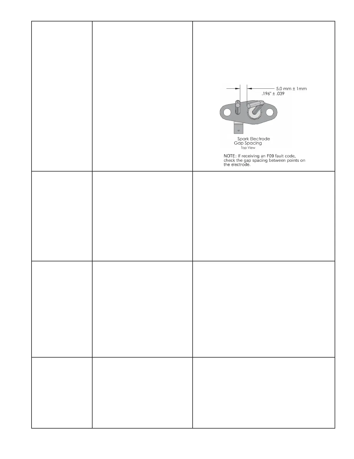
NO FLAME ON IGN F09
PUMP ON
The boiler tried to ignite four times during
one heat call and failed. This is a serious
safety issue as indicated by the illuminated
red light and the word LOCKOUT ashing on
the display. The boiler will not restart until a
technician determines and repairs the cause
of ignition failure and pushes RESET on the
display. During this lockout fault, the pump
will remain on.
1. Watch the igniter through the observation window.
2. If there is no spark, check the spark electrode for the proper
.196” (5.0 mm ± 1mm) gap. See below.
3. Remove any corrosion from the spark electrode and ame
rectier probe.
4. If there is a spark but no ame, check the gas supply to the
boiler.
5. If there is a ame, check the ame sensor.
6. Check any ue blockage or condensate blocks.
FLAME LOSS F10
PUMP ON
The ame was lost 3 times while the boiler
was ring during 1 demand call. This is a
serious safety issue as indicated by the
illuminated red light and the word LOCKOUT
ashing on the display. The boiler will not
restart until a technician determines and
repairs the cause of ame loss and pushes
RESET on the display. During this lockout
fault, the pump will be on.
1. Monitor gas pressure to the unit while in operation.
2. Assure the ame is stable when lit.
3. Check if the display readout changes from “GAS VALVE ON” to
“RUN” within a few seconds of boiler ignites.
4. Check the FLAME signal on the display. It should be above 1.0
when the boiler is ring.
5. If the signal reads less than 1 microampere, clean the ame
rectier and spark probe.
6. If the problem persists and the ‘FLAME” signal is still less than
1.0, replace the ame probe and spark igniter probe.
7. The ame signal should be steady after the boiler has been
ring for 1 minute and is normally at 5.0 to 9.0. If the ame signal
is not steady, disassemble the burner door and check the burner
and its sealing gaskets.
FALSE FLAME SIG F11
PUMP ON
There is ame when the control is not telling
the boiler to run. This is a serious safety issue
as indicated by the illuminated red light and
the word LOCKOUT ashing on the display.
The boiler will not restart until a technician
determines and repairs the cause and pushes
RESET on the display. During this lockout
fault, the pump will be on.
1. Look into window. If there is ame, turn the gas o to the unit
at the service valve and replace the gas valve.
2. If the ame signal on the status menu is greater than 1.0 when
the burner is not lit, replace the spark ignitor and the ame
rectication probe.
3. If the ame signal is not present after turning o the gas
supply, check the gas valve electrical connection.
4. Check for condensate backup. Repair condensate system
as necessary. If condensate has partially lled the combustion
chamber, the refractory wall may be damaged and should be
replaced.
5. Turn the gas on at the service valve after corrective action is
taken.
6. If the refractory wall falls against the rectier probe, it may
conduct the signal to ground, giving a false reading.
FAN SPEED ERROR F13
PUMP ON
The fan is not running at the speed
determined by the control. Fan speed has
been more than 30% faster or slower than
the commanded speed for more than 10
seconds. This is a serious safety issue as
indicated by the illuminated red light and
the word LOCKOUT ashing on the display
.This boiler will not restart until a technician
determines and repairs the cause and pushes
RESET on the display. During this lockout
fault, the pump will be on.
1. Check the combustion fan wiring.
2. Measure DC voltage from the red fan wire to ground while it is
connected to the fan. It should be between 24 and 40 volts. If it is
lower than 24 volts, check for excessive external loads connected
to the boiler sensor terminals
3. Disconnect the 5 pin plug from the fan and check the voltage
on the red wire again. If it is now between 24-40 volts, replace
the fan. If it is still below 24 volts replace the boiler control board.

 Loading...


