24
LP-179 REV. 11.26.14
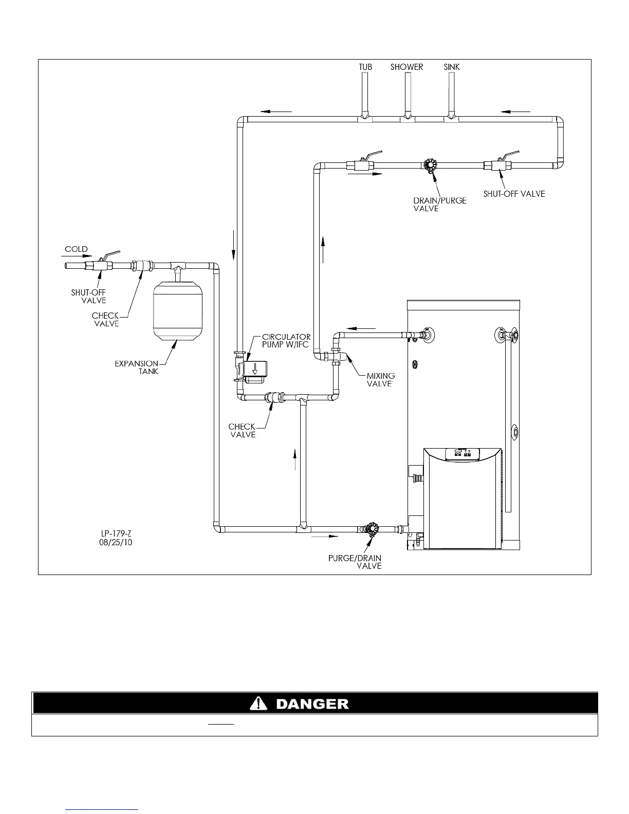
Figure 10 – Phoenix Model with Recirculation Line and Thermostatic Mixing Valve Piping
NOTES:
1. Minimum pipe size should match unit connection size. Upsize pipe accordingly if greater flow is required.
2. A thermal expansion tank suitable for potable water must be sized and installed within this piping system between the backflow preventer and the cold
water inlet.
3. Gas line must be rated to the unit maximum input capacity. Unit must have 10 feet of pipe after gas regulator.
4. All circulators should have an integral flow check.
5. Drains and check valve between unit and storage tank will assist in purging air from system.
6. This drawing is meant to demonstrate system piping only. The installer is responsible for all equipment and detailing required by local codes. In
Massachusetts, you must install a vacuum relief valve per 248 CMR.
An ASSE 1017 thermostatic mixing valve MUST be installed when using outdoor reset. Failure to do so could result in substantial
property damage, serious injury, or death.

 Loading...